CAD
Learn everything you need to be a competent CADDER on 3506 YETI Robotics!
- Downloading Solidworks
- Requirements To Download
- Out with the old, In with the new
- Downloading Solidworks
- Activating your SolidWorks
- Getting Started With CacheCAD
- Drivetrain Design
- Whats next?
- Bad Graphics Card? You can bypass it!
- How To Render Images
Downloading Solidworks
Solidworks is required for robot design and downloading it can be tricky. Here's how to download it step by step.
Requirements To Download
Below are the MINIMUM requirements for a SolidWorks computer, while the bare minimum works the higher the computers stats, the smoother it is to run SolidWorks.
Min 4gb graphics card, (Click here to see all the certified graphics cards)
Min 16gbs ram, (32 GB recommended)
Min 2.7ghz cpu/processor, (Anything above an i5)
These computers are expensive so they are not only meant for SolidWorks, but also everyday use and can also be used in college as well.
If you need help finding a computer or want to find a cheaper one than is on normal vendors look for refurbished computers or message in CAD chat in discord, and someone will help you find a computer in your budget.
Out with the old, In with the new
This is only for students that have previous versions of SolidWorks already on their computer!
First things first, before downloading the newest form of SolidWorks, all previous versions MUST be deleted.
The easiest way to do this is to go to Settings --> Apps --> Installed Apps --> Type Solidworks into the search bar.
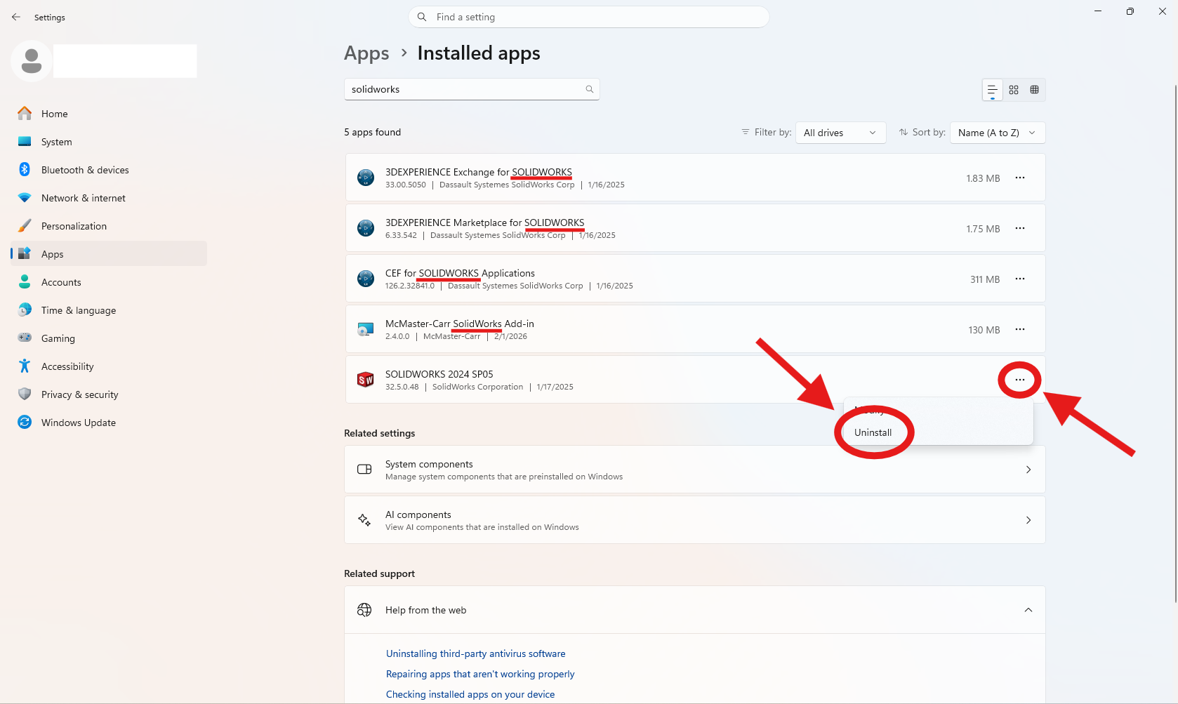
Make sure to delete all add-ons of Solidworks, like 3DEXPERIENCE, as well.
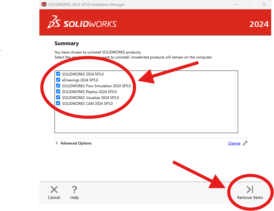
After clicking uninstall, a pop-up will appear on your screen. Make sure all the items in the box are selected and click, remove items.
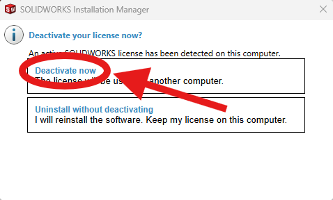
Lastly click deactivate now, since you will be using a new license.
Make sure you have access to internet for a while since the process requires it and takes some time.
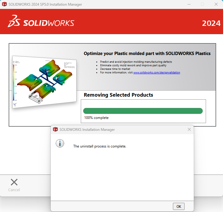
Once you receive this pop-up you are done and can move on to downloading your newest version!
Downloading Solidworks
Now that you have done all the prerequisites for SolidWorks, let's get to downloading!
1. First go to my.solidworks.com and create an account
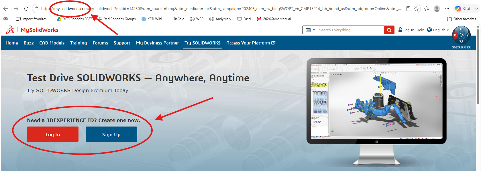
If you already have an account, you can skip this step.
2. Next go to SOLIDWORKS.com/SEK
Fill in your contact information, click Yes for your Serial Number, and select 2026 (SP2.1) for your SolidWorks Version.
Then click Request Download.
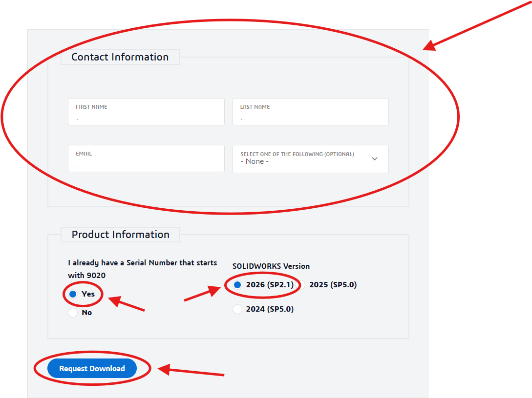
This ONLY applies to YETI student, ask your team for your Serial Number and Version!
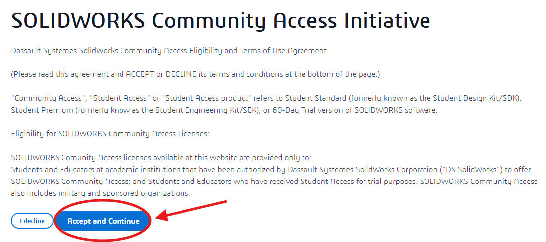
3. Next click Accept and Continue
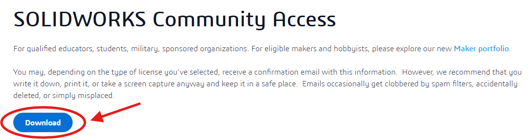
4. And then Download
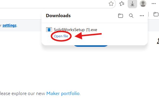
5. You should then see SolidWorksSetup pop-up in your downloads and click Open File.
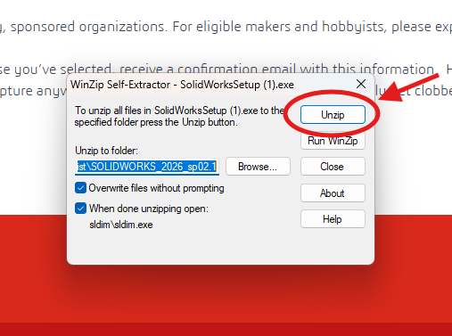
6. A pop up will then show up and click Unzip
7. If it asks, allow the program to make changes to your computer.
8. It may also ask you to reboot your computer. If it does, cancel the installation and restart your computer.
If you do restart your computer, you need to start from step 5 again.
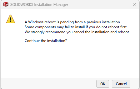
If you get the error a second time after restarting, continue the installation by clicking OK
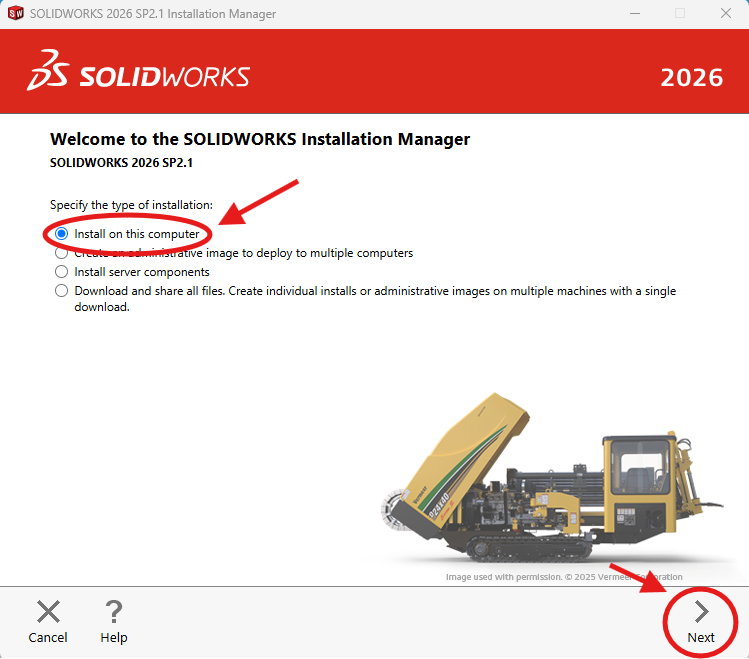
9. Make sure (Install on this computer) is selected and click Next
10. Enter your Serial Number in the space shown below, and click Next
YETI student can find your Serial Number in the pins of the YETI discord CAD chat.
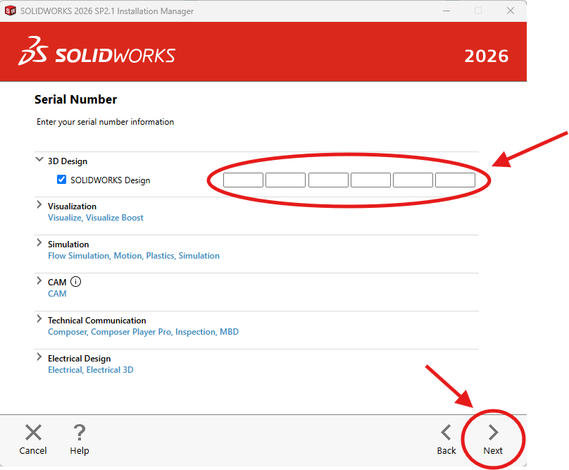
If you are not a YETI student, ask your team for a Serial Number.
11. Click the check on the Terms of SolidWorks and then download and install.
If you are using an old or previously used computer, make sure it has enough storage to hold what you are downloading.
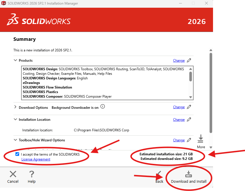
Once again, this process will take time, and you need to make sure you are connected to internet the entire time.
Once it is finally done downloading click finish and we will move on to activating the account!
Activating your SolidWorks
The last step needed to use SolidWorks is activating your account.
1. First find the SolidWorks Design Icon and open it.
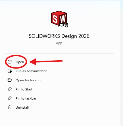
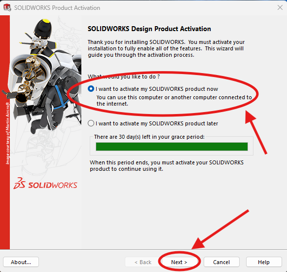
2. Next a pop-up will show up
Make sure (I want to activate my SOLIDWORKS product now) is selected
Then click Next
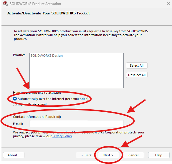
3. Make sure (Automatically over the Internet) is selected, and make sure your email is in the Contact Info section.
Then click Next
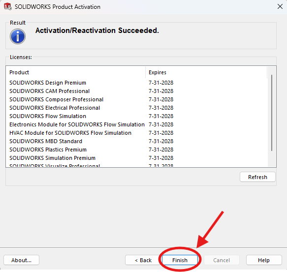
4. After a little bit you will see a (Activation Succeeded) page and click Finish to continue.
If you have any issues with this, send a message and screenshot in CAD chat.
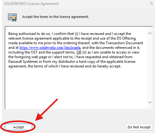
Lastly click accept on the license agreement and you are done!
Getting Started With CacheCAD
CacheCAD is the software we use to manage our files in SolidWorks. Here is how to use it effectively.
1. Installation
Use this installation link: https://drive.google.com/file/d/1BaY2dzd9njdK8UrvhdGPG2ClQ6J_iNNR/view.
You may get prompted by Windows Defender. If this is the case, click the "More Info" button and select Run Anyways.
After installing, you should see this image: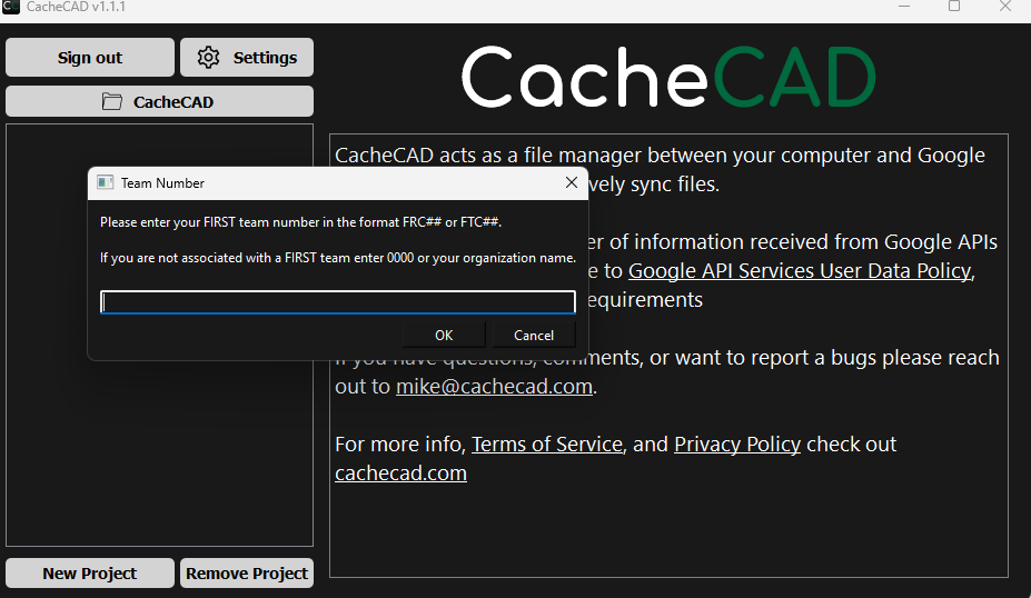
Type "FRC3506" in the field (or FRC{your team number} if you are not on YETI Robotics).
Make sure to sign in with your Google Account in the top left or when prompted.
2. Making Projects
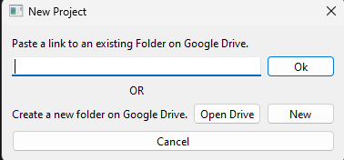
A project allows us to manage our files with Google Drive. To make a project, click "new project" and paste a Google Drive folder link to the field here:

3. Managing Projects
After making a project, it should appear in your left menu. Double click it to see something like this:
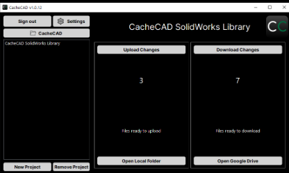
Upload Changes - Changes that you have made in SolidWorks that have not gone to the Google Drive yet.
Download Changes - Changes other people have made that you have not downloaded yet.
Before working, ALWAYS DOWNLOAD CHANGES! This prevents your work from being overridden by others, which is incredibly frustrating. If you can, download at home to save bandwidth at robotics.
In order to save something to CacheCAD, it must be saved locally in your CacheCAD folder, then your Project folder! To access this, click the "📂CacheCAD" button in the top left of the CacheCAD UI, which will take you to the main CacheCAD folder.
To access an individual project's folder, click "Open Local Folder" in the bottom middle. When saving from SOLIDWORKS, always "save as" and navigate to this project folder when saving, or it will not upload it when you upload changes!
When clicking upload and download changes, you can select which changes you would like to make by ticking the boxes. There will be 4 icons next to the changes, which are the following:
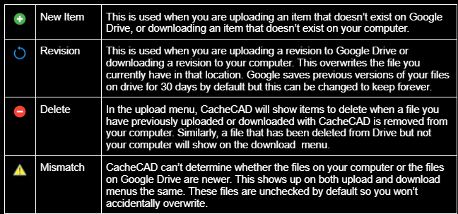
Double-check the symbols before messing with files.
If it was not clear before, ALWAYS DOWNLOAD YOUR CHANGES BEFORE WORKING! I cannot stress this enough: work will be deleted when you do not download changes.
When in doubt, ask a veteran, mentor, or see the user guide here.
Drivetrain Design
Learn about the intricate design aspects of drivetrains
Swerve
Swerve Overview
In FIRST, there are several types of swerve modules which have their own nuances dedicated to specific robot performance
Swerve X2i
- At YETI, we typically use the X2i modules. The 2 is for the 2 motors (one for turning and the other for driving) and the i is for the inverted placement of the motors. This module has a symmetrical gearbox and we prefer them due to their protection of the swerve motors and for the lower center of gravity (CG).
Swerve X2c
- The "c" stands for compact layout which positions the motors closer to each other to optimize the horizontal space. The X2c modules feature an asymmetrical gearbox and use a Kraken X44 for turning and can use an X60 or X44 for driving. Teams typically choose this due to its compact profile and wider wheels which allow for better traction.
Swerve X2t
- The X2t module is slimmer and has an asymmetrical gearbox. The "t" stands for thin layout, optimizing the vertical space. These specific modules take up more of the perimeter space of your chassis, but allow for more central space. This is good for full width intakes and other design choices which require this increase in central availability.
Inverted vs Regular
Regular swerve modules like the X2 have the motors placed above the module, making it more exposed to damage from colliding bots, requiring taller swerve covers (decreases vertical space and adds some weight). Inverted swerve modules are the desired choice as they are nested safely away from the top of the swerve module, meaning we only need a thinner swerve cover for the cancoder (much easier)
Mounting Swerve Modules
Swerve modules are bolted by either a corner mount or a tube mount
- Tube mount - Mounting style which has the 2x1s touching when positioned, allowing for stronger structural support, but the decrease in wheel base causes the robot to be more prone to tipping. You can find this mounting style on the 2025/26 alpha bot.
- Pro - Very structurally strong
- Con - Loss of wheel base and track, making less stable robot
- Wheel base is how far your wheel is distanced from front to back and track is how far your wheel is distanced from side to side, with the wider you go the better CG you accomplish
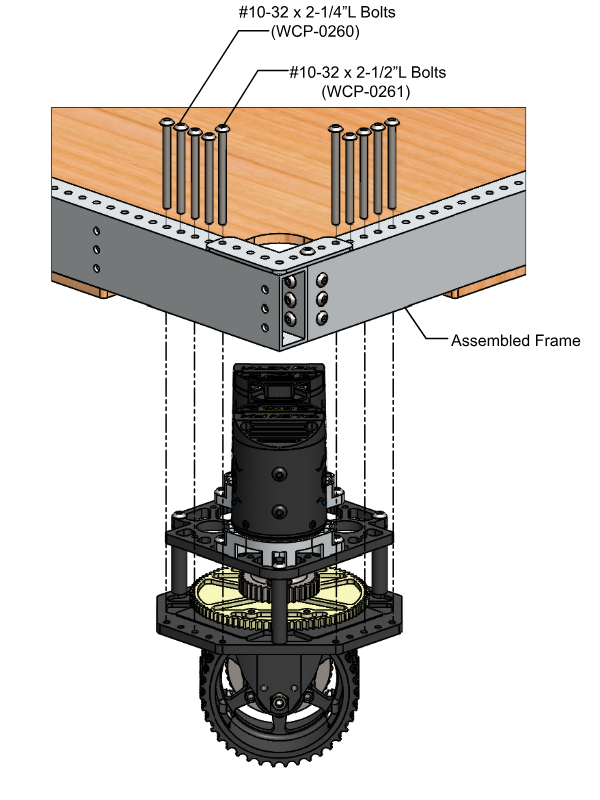
- Corner mount - Mounting style which has the 2x1s spread out from each other, with a gap in between. This increases the wheel base, but makes the overall structural support prone to taking more damage
- Pro - Wheel base spread out more, allowing for better speed and traction
- Con - Less strong, likely to bend plates
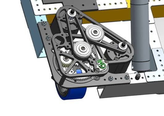
Mounting Choice
- Placing 2x1s under swerve mount allows for lower center of grav
- Placing 2x1s on top of mount good for going over rough terrain and integrating under the bumper intakes (like in 2024)
Frame
When constructing your frame, you'll need
1) 2x1s for the base (Qty - 4)
2) Bellypan (Qty - 1)
3) Frame Rails (Qty - 1 or 2)
Note
Wall thickness of .100" or thicker = thick wall (good for chassis due to durability and high impact resistance)
Bellypan
- Has small holes in certain areas known as grommet holes to allow for electrical components to mount, and has holes along the perimeter for mounting onto chassis. All bellypans have a cut extrusion pattern along the surface which saves weight and makes it look nice, which is known as pocketing
-
- Laser cut by sponsors
- Typically 1/16" to 1/4" in thickness
- Thicker bellypans have smoother driving due to lower center of gravity (CG)
-
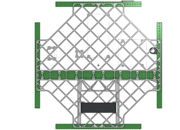
Pocketing
- Process of using a CNC or laser cutter to cut away material from a solid sheet of metal, leaving behind bits of metal known as ribs, which form a lightweight grid or lattice pattern. Common bellypan pocketing patterns include triangles, squares, rectangles and hexagons, but pocketing for other subsystems like shooters or intakes feature different patterns. In SolidWorks, you'd make the bellypan pattern by using the vent tool. As for the mounting holes it would just be a linear pattern which you would cut extrude.
- *ALWAYS have fillets when designing your pattern to avoid difficult to machine sharp edges*
- Any sort of pocketing should have ribs with a thickness of 1/8" to 3/16"
- *ALWAYS have fillets when designing your pattern to avoid difficult to machine sharp edges*
Frame Rails
- Frame rails are mounting tubes (1x1s or 2x1s) which are integrated into the frame design for structural support and for mounting separate subsystems like shooters, intakes, climbers, etc.
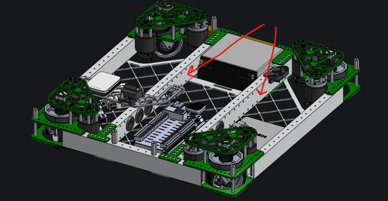
Design Considerations
- Place battery first when designing drivetrain as it is the heaviest component, so you can take CG into account (important for deciding how smooth your robot can drive)
- When designing your drivebase, your main goal should be maximizing CG while maintaining efficient mass to incorporate other subsystems in the future
- Tungsten sheets are heavy and good for CG, but VERY expensive

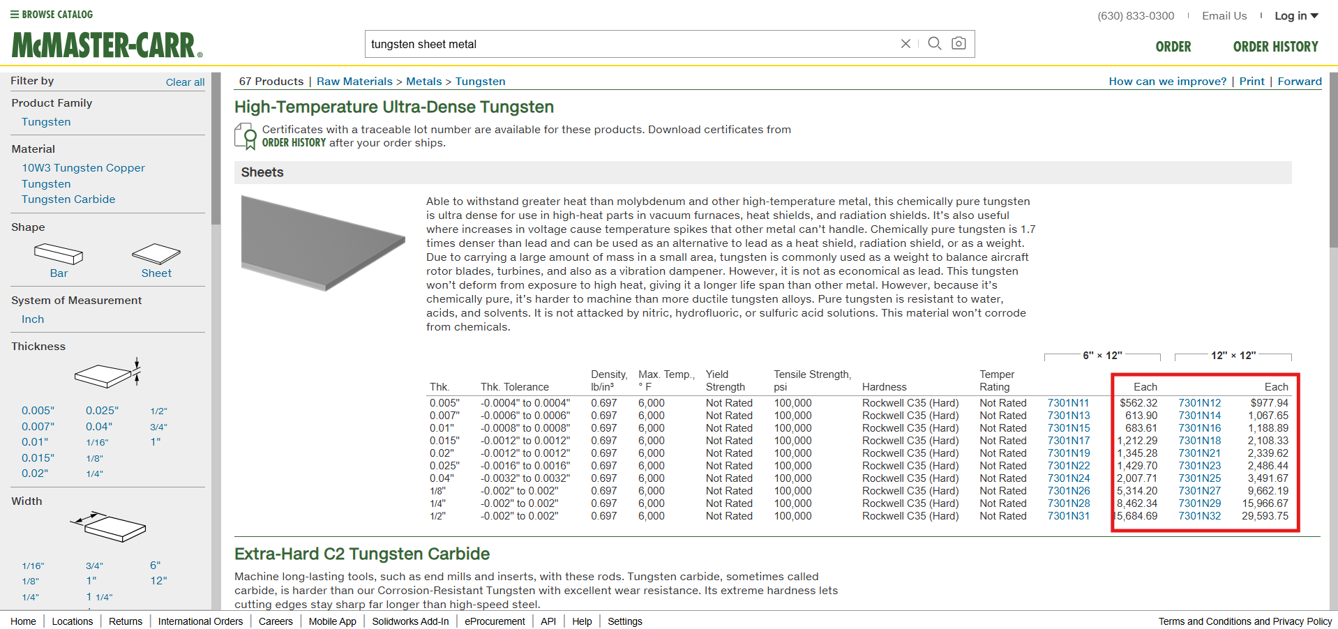
Driving Characteristics
In FRC, every win, draw or loss is contingent on the design choices you make. When it comes to excelling at the game, the number one priority for every team is to drive, and to do it well. For the drivetrain, decisions like mounting your 2x1s above or below your swerve module mounting holes or choosing your bellypan thickness all play a part in your results. So here are some driving characteristics which you should acknowledge when designing:
- Swerve drivetrains are built for maneuverability rather than a pushing tank, which would be the job of a tank drive
- Acceleration is prioritized in games which require lots of change of direction and a need for a fast top speed accumulation
- Tall robots which have a need for speed require heavier drive bases to maintain balance
Gearing
When you design a drivetrain, you can either gear it for torque or for speed
- If your drivetrain is geared too tall, that means it takes too long to reach top speed but has stronger traction
- Robots geared too high will do better with pushing (which can be thought of like torque)
- If your drivetrain is geared for top speed and acceleration, that means it is very fast and can reach its maximum velocity much quicker, but the tradeoff being that it won't win many pushing matches
- Prioritizes speed over torque
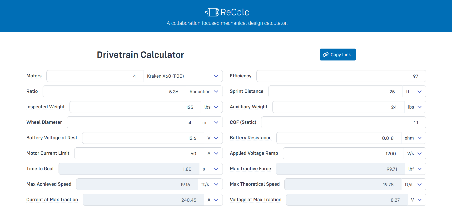
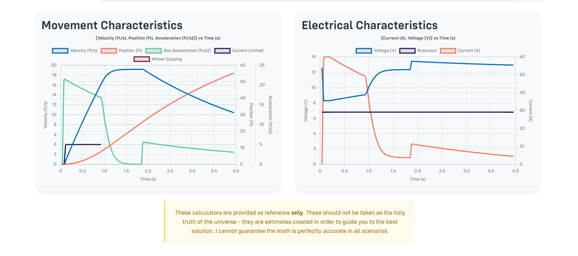
For a deeper dive into drive base design, refer to the Drivebase Design page in the Design Process book.
Whats next?
To learn more about Design navigate to this link to see both a cache and a design course: https://drive.google.com/drive/u/0/folders/1Zmn4XHeXhhq8NJsQPh3pXAXYu101RIQx.
Good Luck!
Bad Graphics Card? You can bypass it!
Step 1: Go to Solidworks Rx
Step 2: Go to Troubleshoot
Step 3: Select "Bypass your graphics card/driver..."
Step 4: Click the "Launch Solidworks" button that is right below it
*Keep in mind that this is needed everytime you want to open Solidworks
How To Render Images
What to do before rendering?
Preperation matters when rendering through SolidWorks visualize. There are 2 main steps to getting it done right.
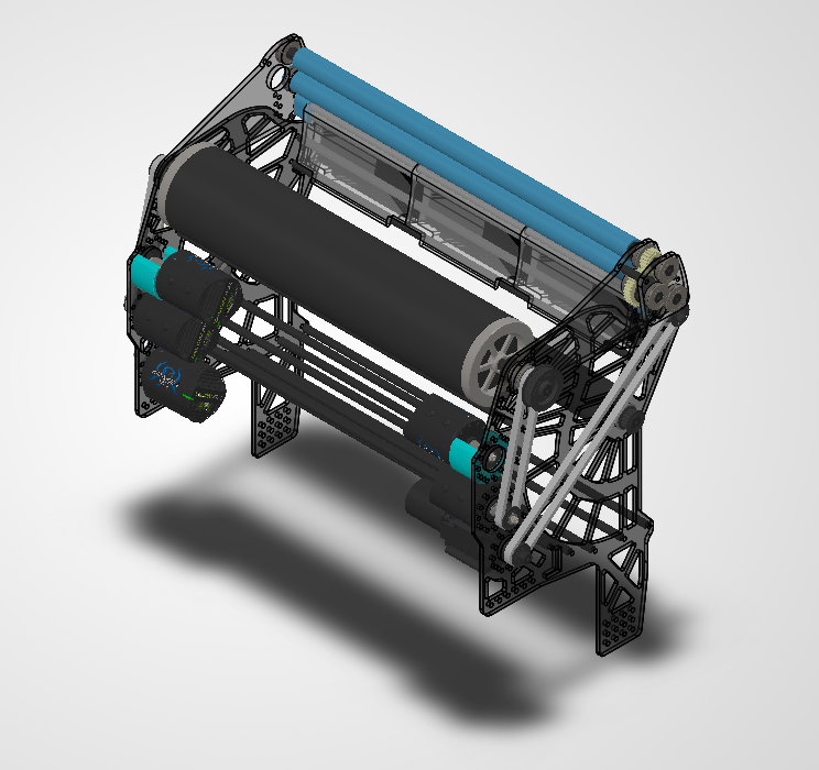
1. First things first, NO hidden parts
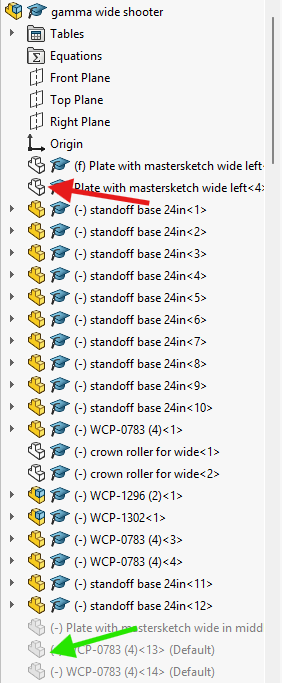
In the software, all hidden part become shown so you should either have everything shown or suppress parts that you don't want to see.
2. The second thing is making sure all parts that have different materials have different colors.
In Visualize, materials are grouped based on their color. So, if your metal parts and your plastic parts are the same color, they will be the same material. This is important because light reflects off each material different and it gives a better look when everything is the right material.
This doesn't mean they can't be similar colors; they can be so close that you can't differentiate them normally, as long as the hex code is different then you are good.
Once you do these two things you can move on to opening the program!
How to open Visualize?
Now that you have a file ready to render, we can move on to opening visualize!
1. First click the setting icon in the top bar of the menu
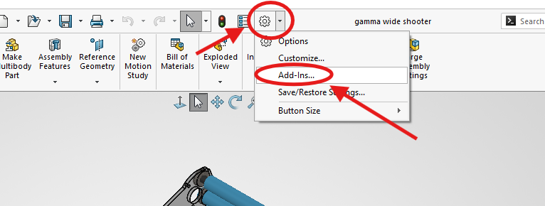
2. Then click Add-Ins
3. Next this pop-up will show up so scroll down till you see SOLIDWORKS Visualize
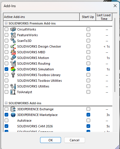
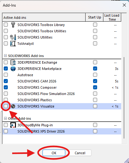
4. Then click the checkmark to the left of SOLIDWORKS Visualize and click OK.
5. Then two new tabs will show up on your top bar, click Render Tools
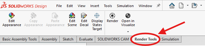
6. Next click the arrow below Open in Visualize and Group by Appearance
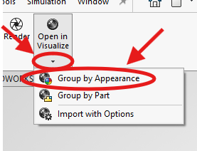
There is a glitch that when you close out SolidWorks then open it up again the Open in Visualize button is there but not clickable. If that is the case, just repeat steps 1-6 again and that will fix it.
7. Lastly you will receive the pop-up below
I would recommend creating a folder for all of your renders and changing the location to your new folder
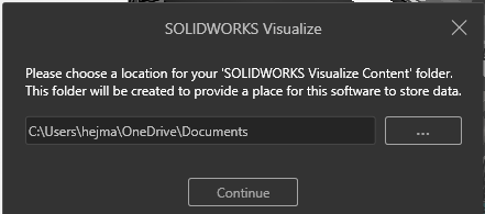
8. Once you are satisfied with the location for your renders click continue to open Visualize!
How to use Visualize
Now that you have visualize open its time to get your photos rendered.
When you first open visualize, there are many buttons and things you will be able to use. But for our need, the most important things are the four below.
The 4 include the preview in the middle of your screen, cube in the top middle, the portrait in the top right, and the paint can to the left of that.
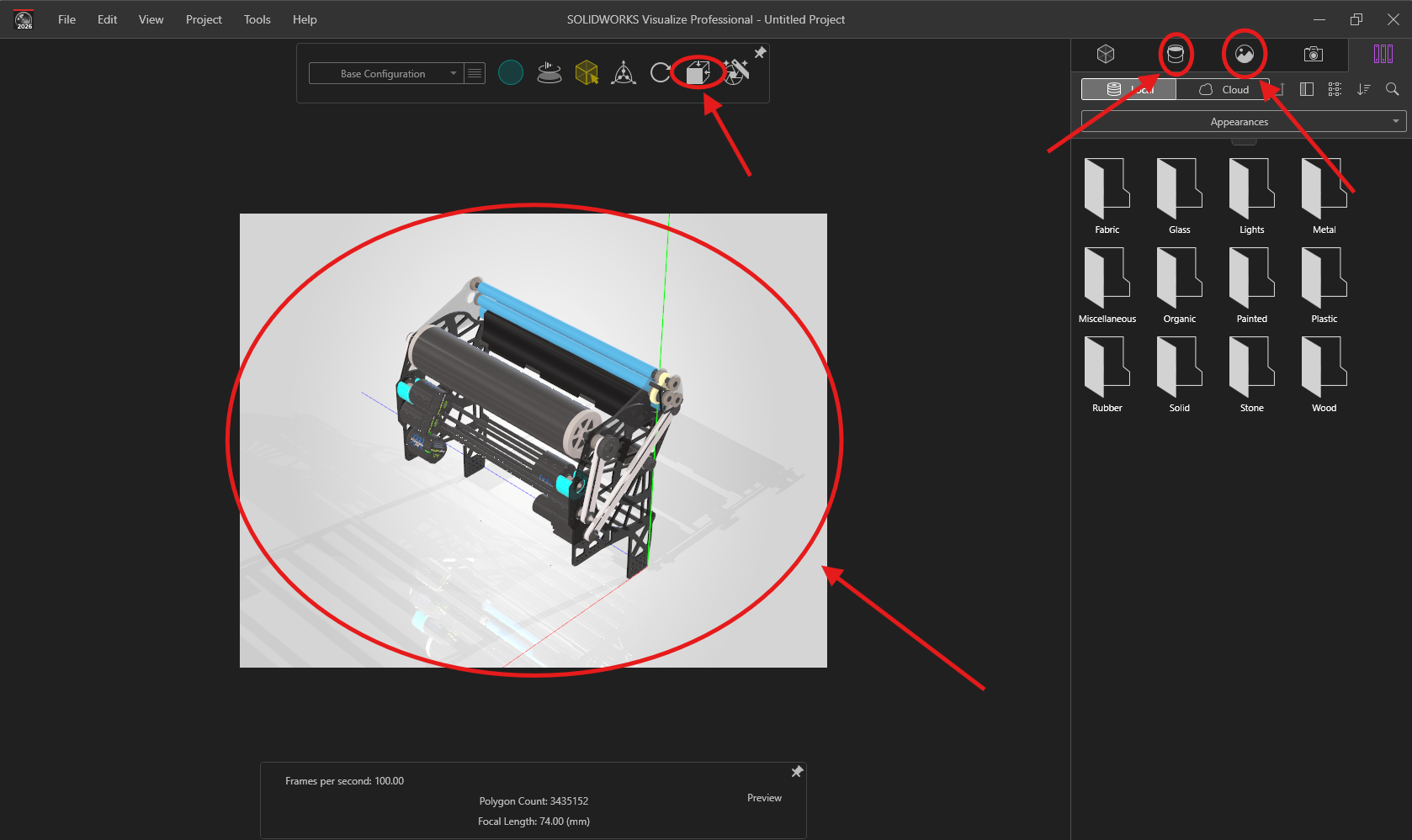
1. The preview is very simple; it acts like the 3d model of your item where you can rotate or zoom in and out.
While it does show some change when settings are changed, it is not completely accurate to the final rendering in the end.
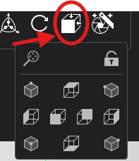
2. Next is the cube, when clicked it pulls up a small screen that allows you to change the POV easily.
Along with that it has the lock icon which stop you from being able to accidently change the POV you want.
3. Next is the paint bucket, there are many things you can do with the paint bucket, but the big one is changing the material.
Like I said in "What to do before rendering", if you made sure all your different materials are different colors then you can use the preview to click on different parts of your item and all parts with the same color will highlight and the color will pop up in Appearances.
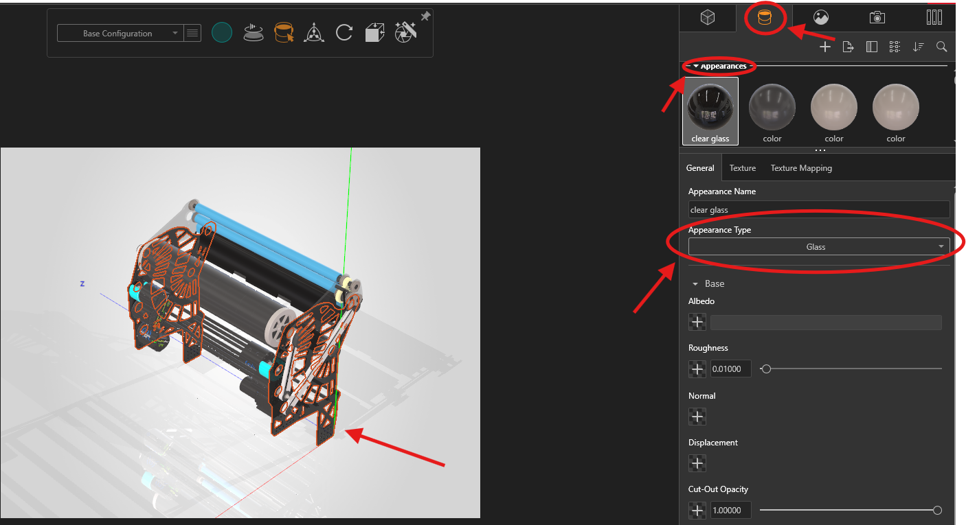
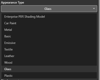
Once you have the part you want selected, click on appearance type.
This will give a dropdown menu where you can select the material you want.
While these three feature are important they are optional to use, only needed to change the POV of the photo to your liking. On the other hand, this last feature has a set of steps that are required for YETI.
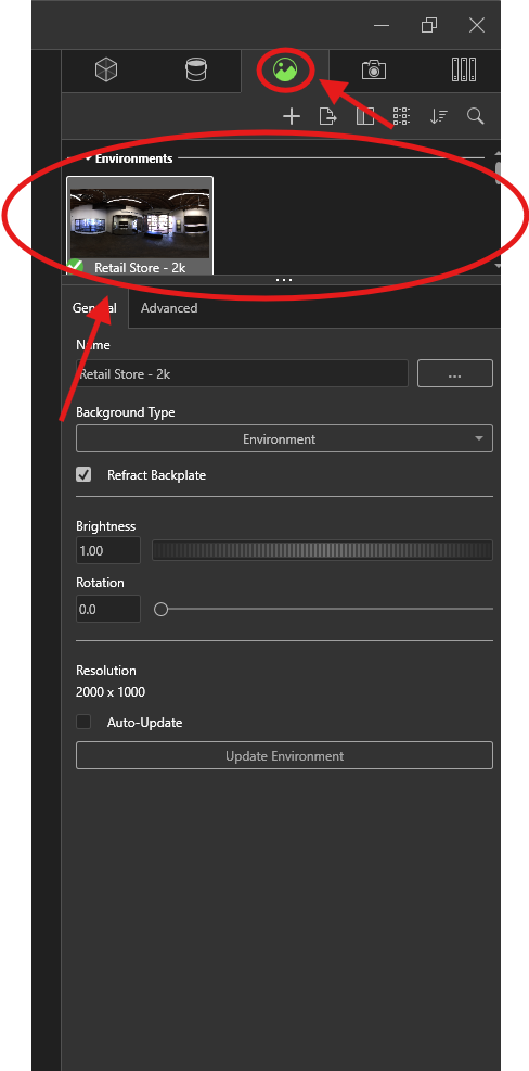
The last feature on the list is the portrait and there is a set of steps you must do to get a good render.
1. First, you need to find the box that says environments and scroll down till you see Backplates.
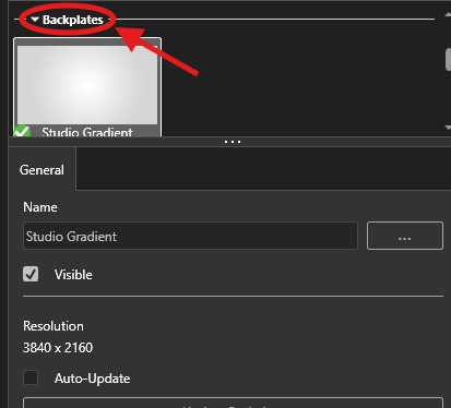
2. Next you will click on Studio Gradient and then the 3 dots next to Name.
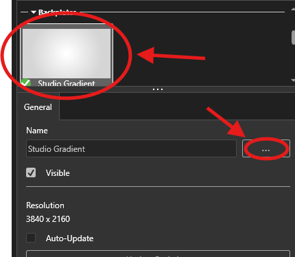
3. Then you need to pick a downloaded photo of a pure white screen from your files.
This can be anything from a screenshot to a download.

There is a white photo above this disclaimer on top of the black line that you can save and download.
4. Once you got a photo selected click open and move on

If your preview turns black just click where it is supposed to be and that will turn it back.
5. Next scroll back up from backplates to environments and click on which ever environment you want.
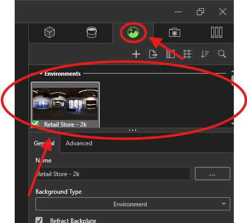
6. That will bring up an advanced option here for you to click on.
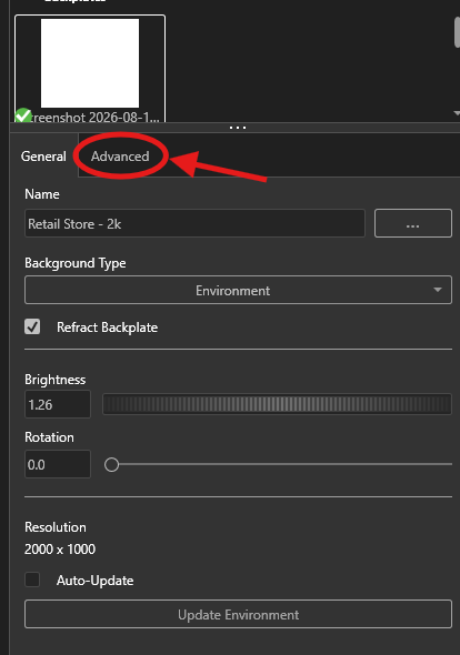
7. That will bring up many different setting but the two most important are Brightness and Shadow Intensity.
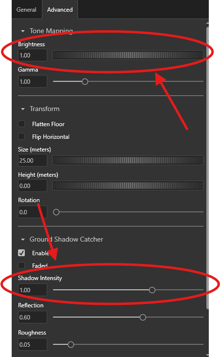
8. First, we will deal with Shadow Intensity, set it to 0 but make sure Ground Shadow Catcher and Faded are enabled.
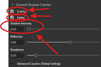
This is because shadows on the ground look bad in photos, but when they are completely disabled the photos look bland. As a solution, setting the shadow intensity to zero and setting it to faded allows no shadows on the ground but still a natural look on the item.
9. As for the Brightness it is up to you, you can make it brighter or darker and render different photos to see what looks best.
Remember that the look you see in the preview is not what it will actually look like so if you want to see how changing the brightness actually changes the photo you will need to render it every time.
Now that all the Visualize settings are all out of the way it's time to move on to actually rendering the image!
How to render a photo?
Now that you have gone through all the steps needed to render a good photo it's time to get the final product!
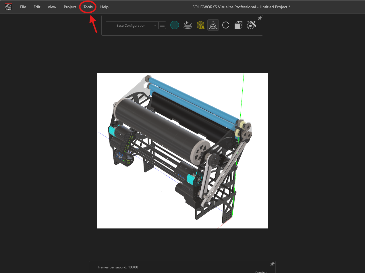
1. On your normal visualize screen you will see a button called Tools in the top left of the screen.
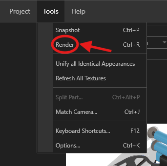
2. When you push the tools button a couple of options will show up including a button called Render which you will click.
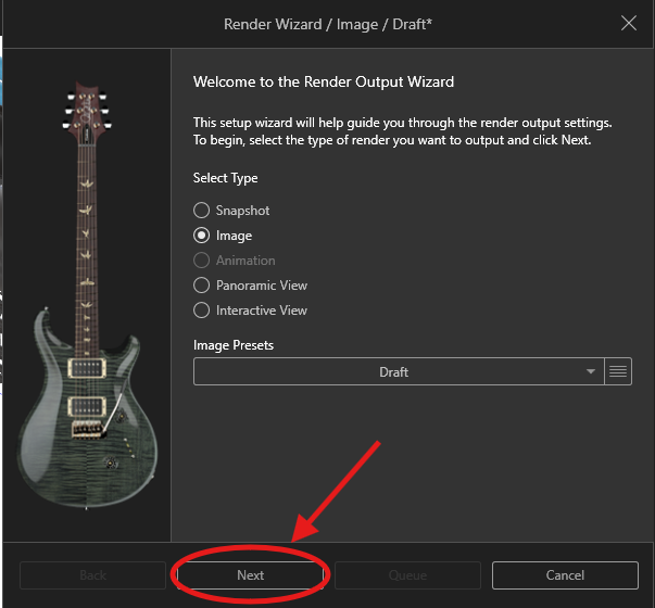
3. That will cause a pop-up to show up, click next.
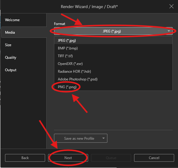
4. Next click on Format, then select the PNG option, finally click Next.
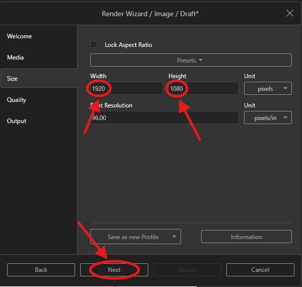
5. On the next page change the Width to 1920 and the Height to 1080 as you see in the photo below.
Then click Next.
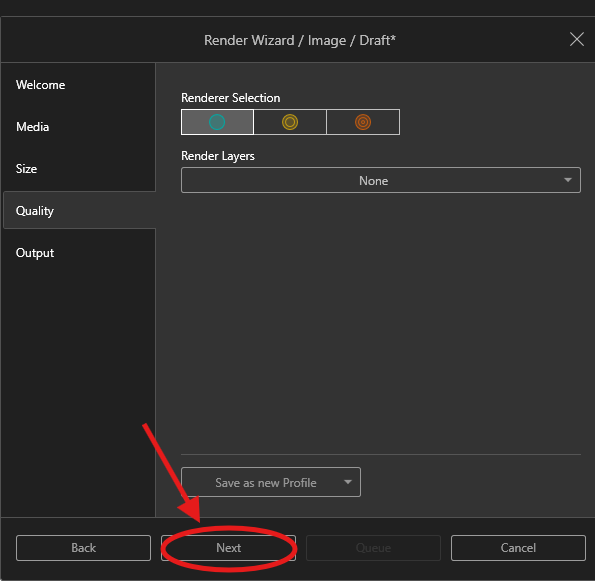
6. Then click Next on this page.
7. Lastly name your file and make sure you have the correct output folder.
Then click render!
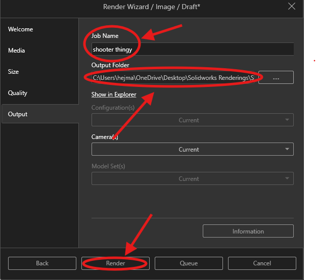
The changes you make in Steps 4, 5, and 7 will save for the project but as soon as the program is closed you will have to reinput those values again.
This will start rendering the photo and show a preview of what you have taken in the output viewer.
The output viewer shows the photos that you have rendered in this project and each render that you take shows up as a separate tab and the left side of the screen.
To take multiple renders you can switch back to the original page by clicking on the tab next to output viewer.
To delete unwanted or extra renders click on the X button on the tab you want to remove.
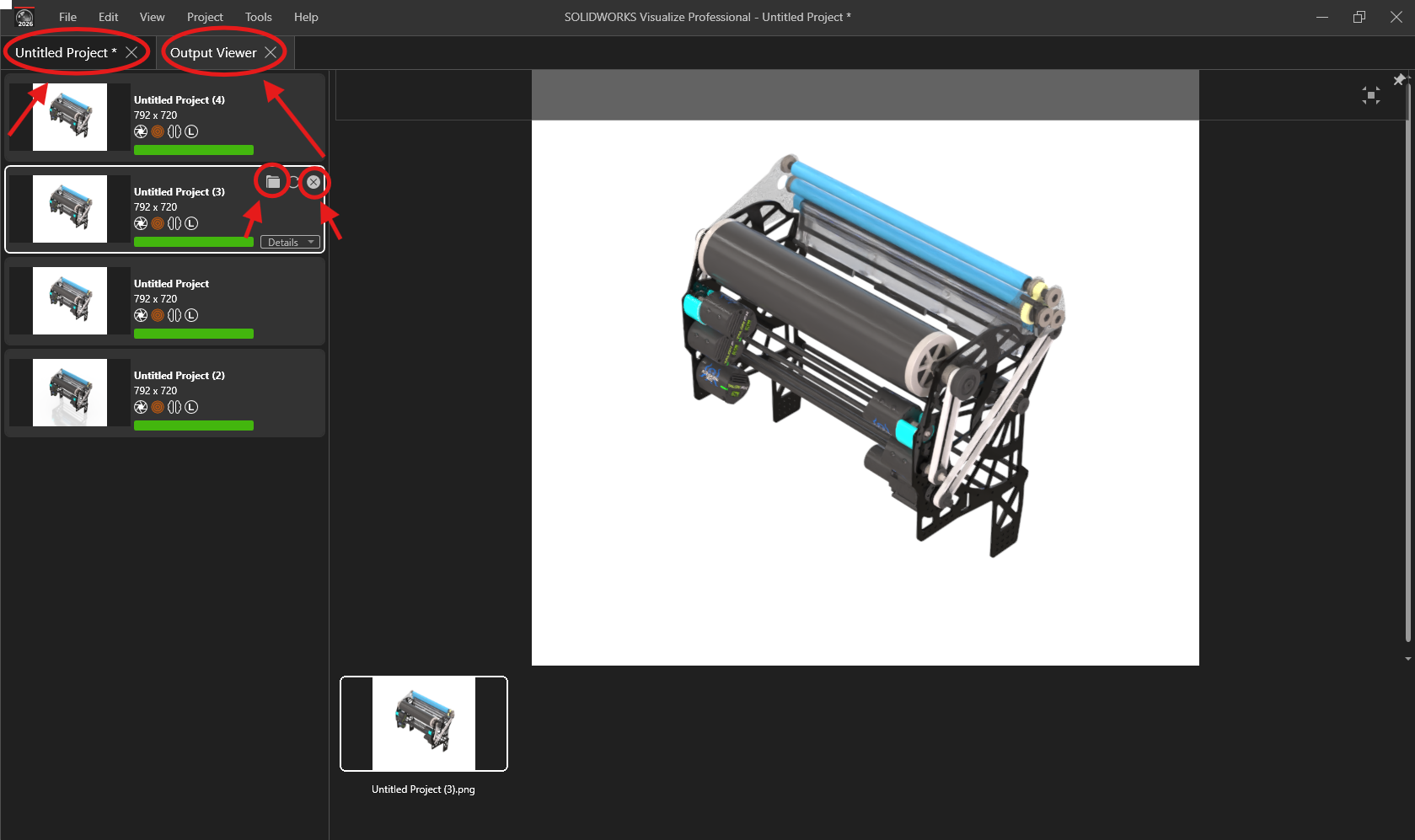
To find the folder that your photos are in you can either click the folder icon on the tab you are on or go to the output folder you have selected to save your photos in, in that folder you will see the SOLIDWORKS Visualize Content folder, open that folder then inside that open the images folder.
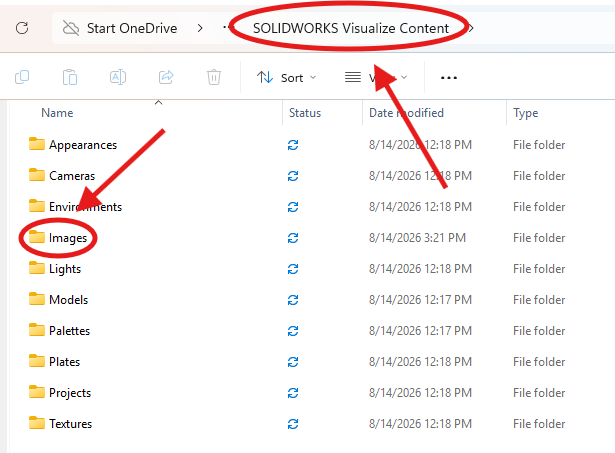
In the images folder you will see all the photos you have rendered.
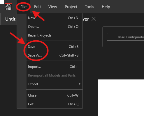
You can save the Visualize project by clicking File and Save that way you can save the changes you made and make more renders later.
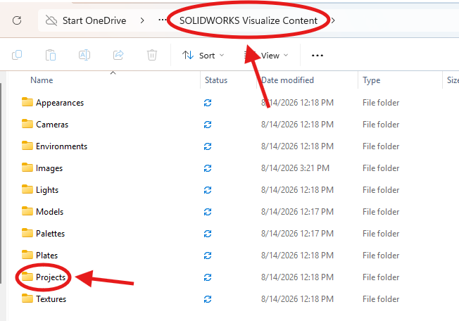
Those projects will be saved in the SOLIDWORKS Visualize Content folder under the projects folder
Congratulations, this is everything you need to know for YETI rendering!