Design Process
How to take a robot from idea to reality! Strat design, technical details, subsystem guides, and more.
- Making Prototypes
- Drivebase Design
- Elevator Design Guide
- Patrick's Rant on why Beluga Sucked (strategically)
- Power Transmission Basics
- Shooter Designs
- Intakes and Linkages
Making Prototypes
When making a robot, we never always land on the best idea first! It is important to try any ideas that seem reasonable before we rule out something and go with a robot archetype. So here is how to try them.
- Sketch out ideas - Drawings are very important as a way to visualize your design and show it to others.
- Keep it simple - No need to add pocketing and fasteners in your drawings
- Add motor/piston positions (if applicable) - things don't move on their own, so leave a spot for motors.
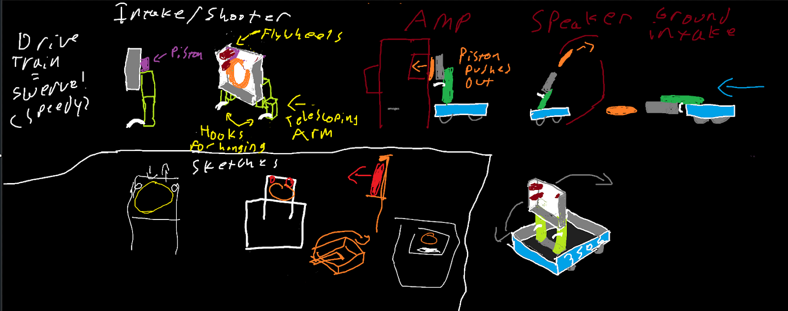
Some drawings for the 2024 season - Crescendo


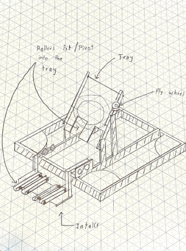
- Cartoon CAD - making some basic CAD of what your prototype looks like lets you test the geometry of your idea a bit more in-depth than a drawing.
- Choose a method to prototype - There are many ways to make a prototype! Here are the most common ones
- Polycarbonate with CNC - Most precise option, ideal for things that need a certain level of precision
- Wood - Quick and easy to work with, never final for robot, very rarely use wood on a final robot
- 80/20 - Good for testing elevators because of sliding, and good for testing compression because of the quick adjustability.
- Other Notes
- When making a shooter, the launch angle and speed are the most important, test from key areas of the field (e.g. bump-firing, firing from a field line, etc.)
- For later prototypes, make sure that your shooter can actually push your game piece in! It can't just use the force to levitate the ball into the flywheel.
- When making an arm/elevator/climber, use a calculator like JVN Calculator rotary mechanism or ambcalc mechanism ratio to find the optimal gear ratios.
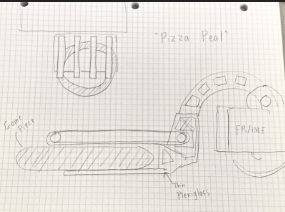
- Some of our previous prototypes:
Drivebase Design
Drivebases
On all of your strategy priority lists, the number one priority should be to drive. This is how to design a drivebase capable of driving well.
1. Drive Type
-
Swerve - 4 wheels, 2 motors each (if you aren't 4414) with one for spinning the wheel and one for aiming the wheel. In 2022-25, these became popular and the standard to be a competitive robot, as the only current holonomic drive which does not need omni wheels, which lose traction and power due to slidiness. Typically two methods of mounting: corner mount (which leaves a gap in the frame and pushes modules further in corner), and tube mount (which brings the module further in and supports the module on the sides entirely).
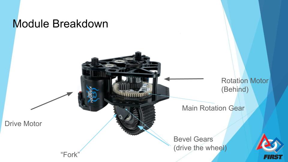
Usually multiple different module types, including
-
Non-Inverted like MAXSwerve seen here. As of 2025, we have never used this style.
-
Pros: Takes up the least space inside drive base assembly, easy to access motors, often lower weight due to less sheet metal.
-
Cons: Easy to access motors for other robots, making them difficult to guard, higher CoG, and take up more space vertically.
-
Inverted Symmetrical like SDS Mk4i seen here. This style has been used on Borealis, Himalaya, K2, Kitty, and Avalanche’s Zelda.
-
Pros: Hides motors from other robots on field under plates, lower CoG
-
Cons: More difficult to access motors, takes up a lot of space inside the drive base, heavier.
-
Inverted Asymmetrical like Swerve X2t seen here. This style, so far, has been used on Beluga and Avalanche’s Frostbyte.
-
Pros: Still hides motors but allows you to push space to one side of the module.
-
Cons: Usually heaviest, difficult to access motors (often more than all other modules).
When to use Swerve:
-
Any game with precise alignment
-
Games with flat field
-
Games with tight choke points and small endgame zones like 2023 (swerve made triple balancing significantly easier).
When to not:
-
Terrain games (unless one of you wants to make pneumatic swerve modules)
- Can't afford it.
- That's it, swerve is amazing for about everything.
-
Tank Drive/West Coast Drive - 4+ wheels (most common is 6 or 8) arranged in two rows on either side of the robot. Either has a middle wheel slightly lower than all of the other wheels or omni wheels on the corners to prevent skidding. Powered by two gearboxes, one on either side, typically with 2+ high powered motors on either side (in the past, we have used 2 or 3 CIMs on either side or 2 Falcon 500s (very similar to Kraken x60s but made by VEXpro)). We have used tank drive on almost every robot 2022 and before.
-
West Coast Drive - A fancy name for tank drive with wheels only supported on the outside (cantilevered)
-
-
-
- Pros - Better for handling terrain (eg. 2016), easy to build (you get a pretty good one in the Kit of Parts)
-
-
-
-
-
- Cons - Cannot Strafe, need to sacrifice speed when turning, have to do a J-turn, much more difficult to drive (unless you are lance).
- Cons - Cannot Strafe, need to sacrifice speed when turning, have to do a J-turn, much more difficult to drive (unless you are lance).
-
-
-
Mecanum Drive - 4 mecanum wheels (omni wheels with 45 degree rollers), one motor on each wheel. Moves and strafes by the differential between each wheel. We only ever used on Wampa (2011), but many FTC teams use it.
-
ngl this is the worst drivebase type, it’s basically a cheaper swerve but guaranteed to be slower since you sacrifice most grip and power due to all-omni drive. For the most part, if you have to run a mecanum drive instead of swerve, just run a tank drive base. You are likely lower down on the pick list, and tank will give you more reliability and defense capabilities (which mecanum does not have because of low grip and speed).
2. Math and Things - One of the most important parts of your drive base is the gear ratio to the wheels. Most COTS gearboxes will have multiple gear ratios to choose from, but you have to buy the right one. When buying a drivetrain gearbox, a low reduction typically means that the motor has a higher free speed but lower acceleration (lower torque). This is better for full-field sprints, but not as good for defense and shorter sprints, especially with high weight robots. High reductions typically have a lower free speed but more acceleration (higher torque), which is good for pushing things, short sprints, etc. However, it is slower on a long sprint. Do calculations with the ratio you intend to use, sprint speed (eg. coral station to reef for 2025, Double Station to grid for 2023, source to midline for shuttling in 2024). Use one of the following calculators:
A. Recalc Drivebase
B. JVN's Mechanical Design Calculator - Make a copy of the most recent
spreadsheet.
3. Mechanical Design - It is important to do all of the following:
A. Make the wheelbase (the area in between the wheels) as wide as possible
within your frame perimeter, helps with balance and tippiness.
B. Design your drivebase to be higher or lower off the ground depending on your
robot. Make it lower if you don’t want to run over things, but if you want to do something like an under-the-bumper intake, make it higher. In general, make it as low as possible to keep CoG lower.
C. Add center support struts if needed, use to mount your superstructure.
D. Make drivebase tubes thicc, banana bars are the last thing you want. At minimum 1/8" wall thickness.
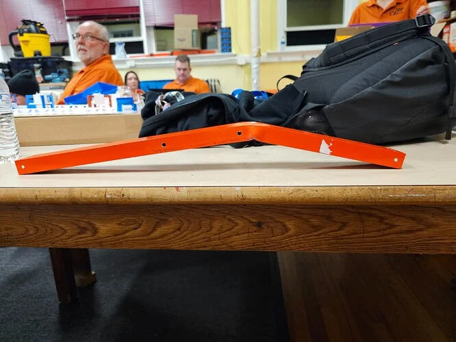
FRC 9496 LYNK's intake frame bar after a heavy collision. At the time, it was made of 1/16" wall Aluminum.
E. Bellypan - In order to keep the electrical work to a minimum, do the following:
I. add mounting holes for major devices (PDH, Main breaker, roboRIO, etc.)
II. Pocket the belly pan (in a grid if possible), to add ribs for zip tie points.
This is also a good method to save weight if needed.
III. Add grommets in center struts to allow for wires to pass through.
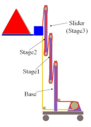
Elevator Design Guide
Elevators - Goal Tall but Robot Short, What Do?
Arguably the most important subsystem to learn for an FRC robot is the elevator, as a solid elevator can make a season run that much smoother. It is typically paired with another subsystem in order to function, usually an intake/end effector of some kind. There are many different (and good) ways to create an elevator, so I will be going over as much as I can.
Essentials
Most elevators in FRC are made of aluminum extrusion, largely 2”x1” or 1”x1” box tubing. There are examples of teams doing other types of elevators (see team 148 in 2018), but mainly teams use 2x1 or 1x1. In that 2x1 and 1x1, you need to use a Bearing Block, or a small part bolted to your elevator with bearings in order to allow the elevator to slide up and down.

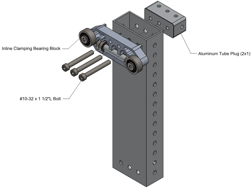

Various types of bearing blocks from West Coast Products. We have used the 1” face clamping blocks (left) on lots of our recent elevators, but have also used the large silver inline blocks (right) on Beluga.
You ALWAYS need contact with all of your bearing blocks in order to reduce friction and remove play, which is one of the main reasons to overbuild your elevator. Different elevator blocks have different spacing between tubes, which is important to take into account when designing stages. As the elevator is driven up, there should be 2 bearing blocks (min) on either side contacting between either stage, usually one on one stage and one on the other on intermediate stages and two on either side for an enclosed final stage.
Design
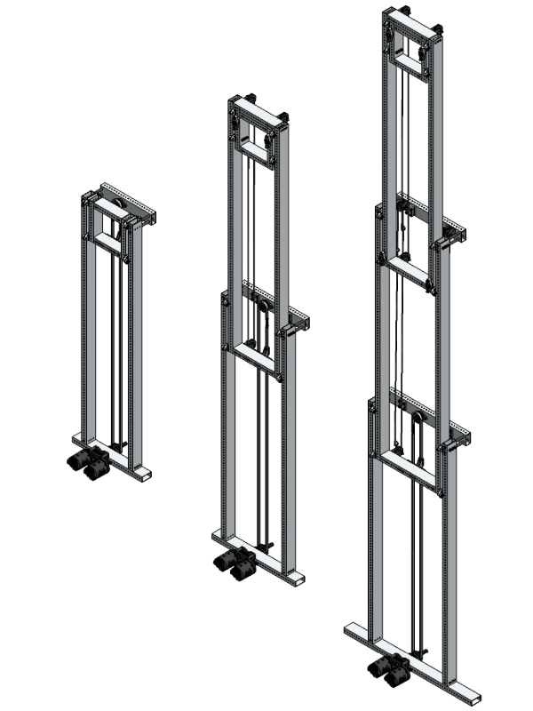
Elevators have many different configurations that are all important to go over. One of the main considerations with an elevator is Stages, or how many moving rectangles are on your elevator to enable its extension. Most elevators have 1-3 stages, but more have been done.
West Coast Products’ GreyT cascade elevator in 1, 2, and 3 stage configurations, respectively.
Stages should never extend beyond each other, but based on the nature of your elevator you should have some Stage Overlap (the distance between the top of one stage and the bottom of another. You can have less depending on how well-built your elevator is to keep contact and prevent swaying, but a good rule of thumb is about 20% of your stage (ex. 30 inch stage height = 6 inch stage overlap).
Elevator stages should always be supported on all four sides somehow, never make a stage without a top crossbar of some sort! This can be achieved in multiple ways:
-
Spacers into 2x1 - Heavy and flimsy, also limits options with elevator blocks on top. Seen on the GreyT Cascade Elevator from West Coast Products, on Himalaya, and on Kitty, which uses smaller 2x1 as spacers.
Source: WCP GreyT single-stage Drawings
-
Fully enclosed (mostly for middle stages) - a full rectangle enclosing the next stage between the top and bottom bars using tube plugs or gussets. Common on middle stages or single-stage elevators especially. we have used this on mid stages in robots like Polaris, Beluga,
Source - Chief Delphi, The Thrifty Bot. Pay attention to the first stage on both.
-
Aluminum support plates - Connect across the two struts to connect away from the internal rigging. Relatively lightweight and good for elevators not needing rigging supported by the top bar (like belt in-tube continuous)
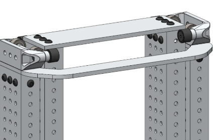
Source: Swerve Drive Specialties.
-
Aluminum side plates + crossbar - Best for base of elevator, leaves a good spot for rigging hardpoints and top sprockets. Usually a 2x1, 1x1, or a long standoff works if there is no need for rigging. Seen on the Thrifty COTS cascade elevator and Beluga.
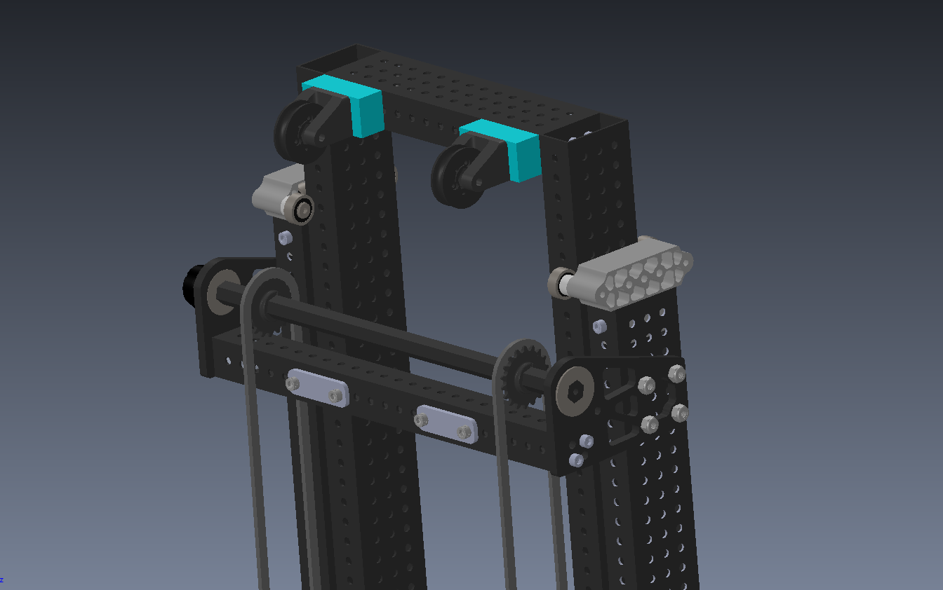
Source - Beluga CAD, using two 3/16" Aluminum plates to hold a 1x1 support, rope hardpoints, and ½” hex crossbar for rigging
Rigging - “I have aluminum boxes, how go up?”
Rigging describes how an elevator is driven, and there are many, many, many approaches to it. Most of them follow some trends, such as what material it uses for dragging the elevator up and down, motor positioning, and rigging types.
-
Rigging Types
There are two main types of Rigging, and it is very important to choose the correct type.
-
Cascade Rigging - Cascade rigging involves multiple separate loops for interacting with one stage to the next. Each stage will move the same distance from the previous stage as all others, giving it unique movement on each stage. This also means that there will be 2x force on the first stage, and the final stage will move faster than the first stage. These elevators are mostly run with Chain on the first stage and Dyneema for the rest.

Source - FRCDesign.org
Pros of Cascade Rigging
-
More Commercial, off-the-shelf (COTS) solutions, meaning less custom stuff.
-
Examples - WCP GreyT elevator, Thrifty Elevator.
-
Different ratios enable some extra functionality (eg. in 2018 climbing with the first stage due to its higher force, see 2056 in 2018).
-
More flexible with motor location (eg. can go parallel or perpendicular to elevator).
Cons of Cascade Rigging
-
Higher Center of Gravity due to the middle stage moving with other stages.
-
Complicated rigging at 3+ stages, making more stages than 3 difficult.
-
Continuous Rigging - Continuous rigging involves 1 or 2 loops running through the entire robot. This results in the stage with the least friction (should be the final stage if designed well) moving first, followed by the next stage, then the next, etc. Requires a hardstop at each stage. Typically can move faster for short extensions due to no force moving the middle stage up. Mostly either used with Dyneema and pulleys/spools or Timing Belts with pulleys.


Source: Chief Delphi, FRCDesign.org
Pros of Continuous Rigging:
-
Easier to add stages (able to just run the line through another stage)
-
Can make the rigging very out of the way (a common way to rig continuous elevators is with the line going through the tube)
-
Lighter weight (in comparison to chain)
-
Low Center of Gravity since the top stage does not move until needed.
-
L O U D (makes a “clank clank clank” sound due to hitting the hardstops sequentially).
Cons of Continuous Rigging
-
More difficult to design since limited COTS support, results in lots of designs
-
More expensive (one belt for continuous elevator can cost upwards of $200 and more custom parts means higher cost)
-
Less flexible with gearbox options (needs to be perpendicular and directly under the elevator for a lot of setups)
-
Requires less play and a whole lot of tensioners in the system.
-
Since it is all one belt/rope, ensuring both sides are taught is one of the main struggles of designing continuous elevators. Often seen are idling pulleys, cam-based hardpoints, and ratcheting straps.
-
Rigging Materials
-
Chain - Very common in cascade elevators, chain is typically found in two flavors: #25 (or #25H for slightly more strength) and #35, both of which need a sprocket at the top and bottom of your elevator. Very rigid and easy to tension due to inline tensioners, but weighs a lot. Hardpoints are threaded through the chain, like with the Thrifty #25 Comb.
-
Rope (typically Dyneema/UHMWPE) - On most elevators, used in middle stages. Very lightweight and runs on pulleys, and a ratchet is typically used for tensioning with a hardpoint either tied or clamped on the robot, like a WCP ratchet block.
-
Kevlar Timing Belt - The most uncommon, belts are largely only used in continuous elevators. Though slightly more precise and rigid than rope for continuous, it is thicker, more expensive, and requires more legroom to run a 1” wide belt vs a ⅛” thick rope. Heavy use of idler pulleys for tensioning and hardpoints used to engage teeth on the end of the belt, often on cams for tensioning.
3. Gearboxes
For gearboxes, there are many considerations to be made. The first of which should be how many
motors you are using. Most use 1-2 high-powered motors, like a Kraken x60. Next, decide on your
packaging. Are they running parallel to the elevator or perpendicular? Next to each other or on
opposite sides? All considerations to be made. Then, calculate your gear ratio needed. Use either
Recalc Linear Mechanism Calculator or JVN's Mechanical Design Calculator to get the desired
ratio. You are calculating the time to go up. Try to optimize the time to get up while getting the gear
ratio smaller and smaller until the time to extension starts to decrease. (note: make sure to use
current limits when calculating! The most supply current a modern motor can take is 40A
with the correct breaker, but you should try to be as low as possible. 10A is a good supply
current limit if you don’t know anything.)
Examples
-
Continuous Elevators:
-
8727 Glitch 2.0’s 2025 Elevator - Belt In-tube 2 stage elevator driven by 2 NEOs on planetary gearboxes.
- 1690 Orbit's 2025 Elevator - A very fancy Belt Differential elevator which uses the belt driven by two motors to both drive the elevator and pivot the arm.
-
3847 Spectrum -△◅’s 2023 Elevator - External Belt 2 stage elevator with CF Springs on 1 NEO on planetary gearbox
-
6328 Mechanical Advantage's 2025 Elevator - External Cord 3 stage elevator on a huge drum driven by 2 Kraken x60s on two custom gearboxes.
-
4522 Team SCREAM's Elevator - Belt In-Tube 2 stage elevator driven by 2 Falcon 500s on a custom gearbox.
-
Eliot (111 Wildstang)’s Elevator - Belt In-Tube 3 stage elevator driven by 2 NEOs on planetary gearboxes
-
Cascade Elevators:
-
West Coast Products’ GreyT Elevator - Chain and Dyneema 1-3 stage COTS elevator kit driven by 1-2 Kraken x60s on WCP gearbox.
-
1678 Citrus Circuits' 2019 Elevator - Dyneema-only 2 stage Cascading elevator driven by 4 775pro Motors on custom gearbox.
-
9062 Critical Circuits’ 2025 Elevator - Single stage Chain-driven elevator driven by 2 Kraken x60s on planetary gearboxes.
-
FRCDesign.org’s Sample Elevator - 3-stage Chain and Dyneema elevator driven by 2 NEOs on planetary gearboxes.
- The Thrifty Elevator - Chain and Dyneema 1-2 stage elevator driven by whatever gearbox you want.
Patrick's Rant on why Beluga Sucked (strategically)
(intro tl:dr - having a high skill ceiling means you need to get to that skill ceiling. Simple robots can get going faster and are easier to make)
In 2025, we made the robot Beluga. Though a capable robot, it had one main problem. It had far t̸͚̮̥͙͓͒̋o̷͇͚̔̆o̶̢̝͕̠̘̒͝ ̷̲̑̄m̷̹̯͉͍̽̃̓̚ͅǘ̸͓͖̊̚͝c̷̞̤̪̩͔̍̀ḥ̸̛̤̎͋̽ ̷̠̳̓̃͋͝g̵̭͎̓͐̄̓̚o̸̘̳̐͆̚i̶̗̙̤̳͈̋ṅ̴̟͖͓̪͕̆̎ģ̷̨̝̲͒̍͐̎̈́ ̸͕̲̥̟̅ǫ̷̛̟͈́̓̕n̷͙̫̈̎̀͝. Degrees of Freedom, or DoFs, are a measure of how many different directions a robot can go in. To be competitive, you need to balance how many DoFs you have with how capable a robot is. When having many DoFs (like Beluga), a robot may gain a higher skill ceiling (the absolute max potential of a robot), which will help at extremely high level play, such as division playoffs, given the time. We used the high skill ceiling to justify building such a complex robot, as we believed that the ground intake of 2025’s game piece (a 1 foot long segment of 4.5 inch OD PVC pipe), as teams like 1690, 2056, 27, 4414, and 1678 did. The catch?
All of the teams listed above have World Championship division wins and have a history of winning almost every event attended. Some are even world championship winners. In contrast, our team has won 4 in-season events, only one of which past 2017. They make complicated robots in order to max out at the highest levels of play. We have never reached the same level as these teams, and don't need to make the same complicated and ultra-capable robot for North Carolina.
Beluga
(tl;dr: too much going on)
It is important to take into account how much capacity your team has to push the robot to that skill ceiling. That means a lot of things need to happen, and fast. Getting a robot to its skill ceiling means designing, building, and wiring the robot needs to happen as fast as possible to give time to programming. Beluga was “finished” in approximately Week 6, which gives programming 3 weeks to program a significantly more complicated robot than we have done before. Not including the drivebase, Beluga has 4 DoFs, 3 of which are essential to basic scoring.
-
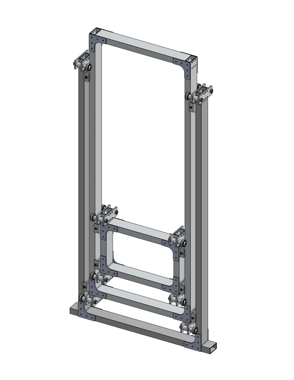
Vertical 2-Stage Cascade Elevator
-
Rotating ~2 ft long arm
-
Intake Wrist on the end of the arm, theoretically 90 degrees range of motion either way.
-
Climber (doesn’t concern main scoring so not essential)
This meant for a full cycle, all of the following had to happen (minimum)
-
Rotate arm to HP intake
-
Rotate wrist 90 degrees
-
After intaking coral, re-rotate the wrist to 0 degrees
-
Bring arm back to vertical
-
After driving to the reef, extend the elevator up.
-
Rotate arm 45 degrees
-
After alignment, rotate arm further down to score
-
Move elevator down
-
Stow arm
That is a lot to do in terms of programming, and took many iterations to get functional. Optimizing every action here is a lot of work that would require lots of programming time and labor, which we did not have at the time.
An image of Beluga:
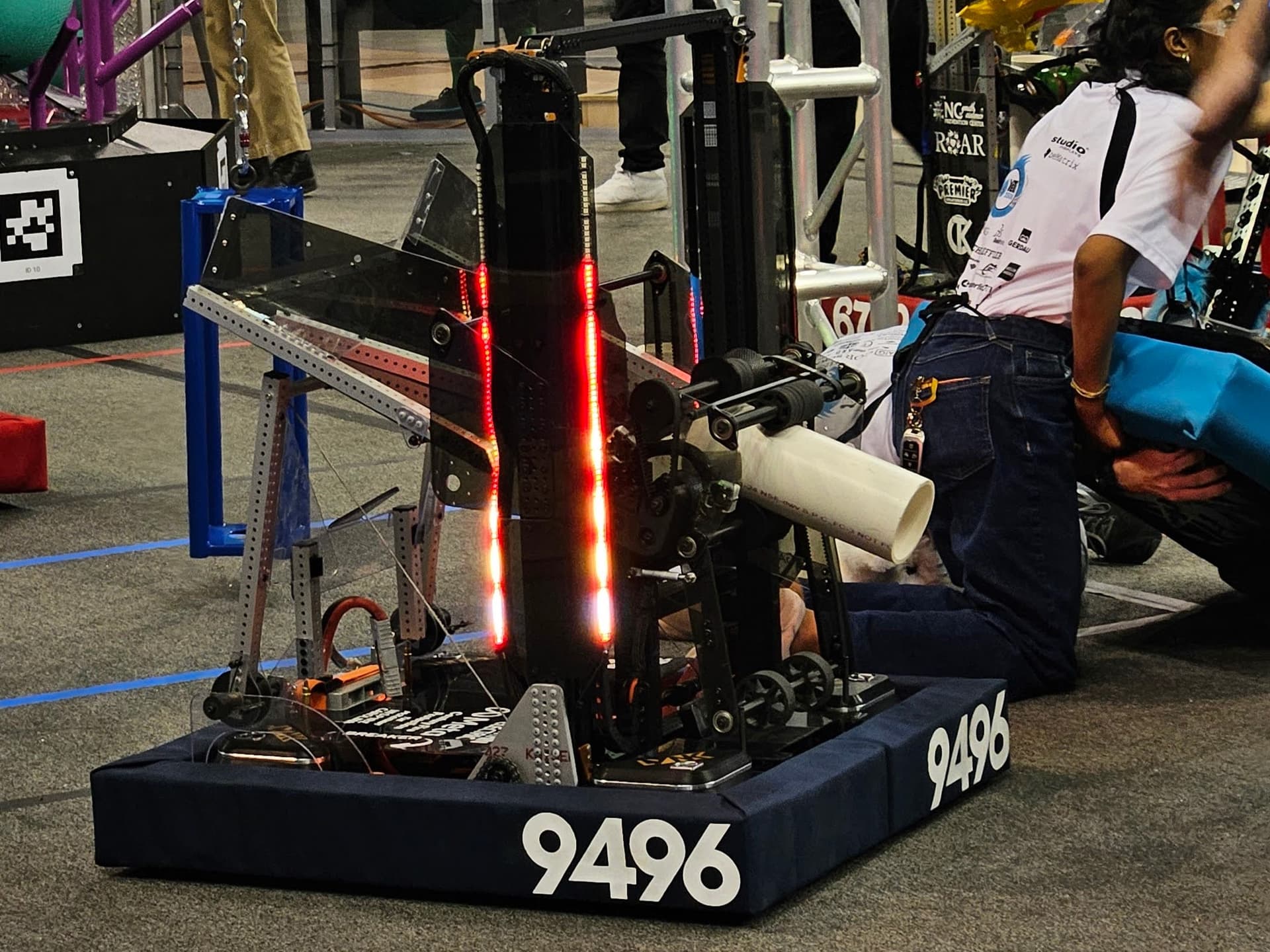
Rocky
(tl;dr: simple fast bot wins in NC, this ain’t California)
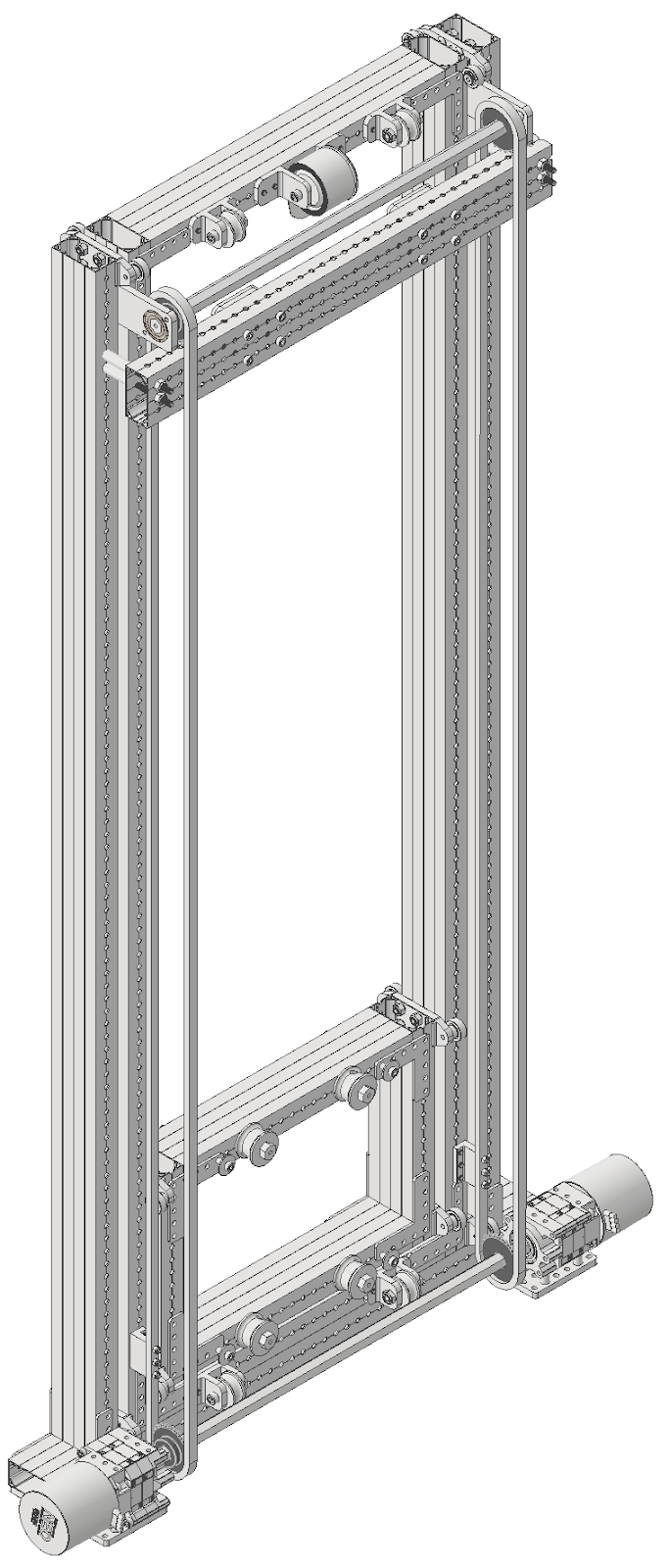
At our first two events, team 9496 LYNK absolutely dominated the bracket, not dropping a single match and winning as the Alliance 1 Captain. So how did they do it? Are they mentor built? No, their students clearly put in a lot of time. Are they more experienced than us? No, they joined in 2024! Does each of their students have a 254 IQ? Nope. They approached the problem with better strategic design than us. Their skill ceiling, though high, was (arguably) lower than ours. They focused on simplicity in their design, which gave them a high skill floor, meaning how capable something is out of the gate. It also meant that they had less subsystems to design and build. At its first event, Rocky had a grand total of 1 DoF - Their 2-stage Belt in-tube continuous elevator (later added a climber), meaning they had a total of 2 actions to score:
-
Move elevator to correct scoring height
-
After spinning wheels, drop the elevator again.
An image of their robot:
This meant that they needed very little to tune and could get up and running much faster. It is evident how far ahead of us they were at our district events. To quote a member of theirs, "LYNK adds DoFs like amendments to the constitution". Meanwhile we add DoFs 2 weeks before the first competition (Beluga originally did not have a wrist until about week 1 of competition)
Us versus LYNK at 2025 Mecklenburg District Event: https://youtu.be/MbUwNeuftS8?si=cNCRRYHEQOvEYJDZ
You can clearly see how they were much faster than us because of their low skill floor.
Habits
(tl;dr: this is not new for us we always build complicated robots for NC)
This is a common theme for us when making robots, using many degrees of freedom often makes us less competitive than we could be by designing cleverly. Some examples:
-
2024 - Kitty (an abomination) - Had 3 DoFs not including climber (slapdown intake, pivoting shooter, cascade elevator). Did okay but took too long to build and broke consistently (lots of points of failure like intake belts, bent shooter plates, handoff sequence failing, cracked polycarb intake plates, etc.
-
Winning/Finalist robots in NCCMP:
-
9496 LYNK - no DoFs, only spinning wheels.
-
4795 Eastbots - 1 DoF (pivoting shooter)
-
2642 Pitt Pirates - 2 DoFs (slapdown intake, pivoting shooter)
-
8738 SLICE - 1 DoF (pivoting shooter)
-
2023 - Himalaya (imo our best recent robot) - Had 3 DoFs (pinchy intake, diagonal elevator, flipping end effector on elevator). Handoff from pinchy intake to end effector was nice for doing ground but slowed us down immensely vs other robots (see: 2023 UNC Asheville Playoffs Match 4). Got way faster with just doing HP intake with the end effector and swapped pinchy intake to cube-only slapdown intake which was good for 3 piece auto, got us very far (finalist at Meck + DCMP, first time as first pick at worlds).
-
Winning/Finalist Robots in NCCMP:
-
7890 SeQuEnCe: 3 DoFs (Double-Jointed arm plus end effector pivot)
-
587 Hedgehogs: 2 DoFs (diagonal elevator plus linkage end effector)
-
4795 Eastbots: 3 DoFs (arm + end effector pivot + extra simple slapdown intake)
-
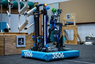
3506 YETI Robotics (yk this one so bonus robot:)
-
Next highest EPA: 5727 Omegabytes - 2 DoFs (double-jointed arm)
Takeaways (read this if nothing else)
-
Less is more: doing something insanely fast out of the gate will be more competitive for district events.
-
Build fast: simple robots are easy to build, meaning that programming gets more time with the robot, driver gets more practice, etc. Also means eventually you will optimize your robot, whereas with Beluga we got nowhere close.
-
Simple is reliable: having less subsystems means you have less failure points, resulting in more reliable scoring (and winning).
Power Transmission Basics
Power Transmission Basics
A Power Transmission, for the most part, allows rotational motion to be altered and moved around a mechanism. This allows for a mechanism to be far away from a motor and have more speed or torque than the motor outputs. Think about a bike chain, which can have its torque increased or decreased by moving to a larger or smaller sprocket on its casette. This works similarly, just on a smaller scale.
Ratios
These allow us to modify the torque and speed of a mechanism by making one rotation take longer than the other. This is by using the properties of a circle, and making the rotation of one gear take longer/shorter than the next. Watch this video for a pretty good explanation. A reduction indicates that the input gear is smaller than the output gear, which means that the torque increases. Conversely, a step-up indicates that the output is smaller than the input, making a mechanism speed up with less torque. Ratios can stack, such that many gears next to each other multiply.
For example, a 12 tooth motor pinion interacts with a 48 tooth gear, creating a ratio of 4:1. On the same shaft as the 48 tooth gear, a 24 tooth gear drives a 60 tooth gear on another shaft, which has a ratio of 2.5:1, resulting in an overall ratio of 10:1 by multiplying the two.
Gears
An example of a two-stage gearbox. Notice the difference in rotation speeds of the gears and their directions.
Gears are used for two primary purposes:
-
Gear Ratios - By having a large amount of teeth and directly touching each other, it allows for a lot of compact reduction that is more reliable than chain or pulley.
-
Inverting motion - Input and output gears spin opposite to each other, allowing one mechanism to make two things spin in different directions.
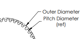
Most gears have the following important dimensions
-
DP (Diametrical Pitch) - how many teeth in one inch. Most FRC Gears are 20DP, but 10DP and 32DP are also seen sometimes.
-
Pitch diameter - how far the center is from where the next gear should interact with the gear. When making center to center distances for gears, use Pitch Diameter.
-
Outer diameter - The actual diameter from the center of the gear to the outside of the teeth. This should be used for clearances.

Chains
An example of a one-stage chain reduction, with the large sprocket rotating much slower than the small sprocket, but notice the chain moves the same speed all around.
Chains are best for when lots of torque needs to be transmitted across a distance. They use a loop of chain around 2+ sprockets, which turn with the chain. Often seen on large mechanisms like elevators, arms, slapdown intakes, or tank drive systems. However, some downsides is that they must be tensioned with either an idler sprocket, which is a sprocket that presses against the chain loop to keep it tensioned, a Cam to physically move the sprockets away, or an In line tensioner, to make the loop tight by shrinking its length.
They have the following important dimensions:
-
Pitch - the distance between the centers of two cylinders in the chain. The most common in FRC are #25 and #35 (.25in and .35 in pitch diameter, respectively.)
-
#25 vs #35 - #25 is lighter and has smaller sprockets, but has a lower strength compared to #35, which is approximately 3 times heavier. If you wanna use #25 chain in a high load environment, #25H adds some tensile strength and still works with #25 chain by simply adding a plate to the chain.
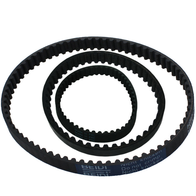
Belts
Belts are typically found in places where not much reduction is needed, but the motion needs to be transmitted to another spot. Belts interact with Pulleys, which turn a belt’s linear motion into rotational motion. They are often found in roller wheel systems, as they are extremely light and easier to package than chains. There are multiple types of belts, but the most common in FRC are the following:
-
Timing Belts - Belts with rounded teeth to interact with a toothed pulley. These have the least slip and are most efficient with power. Most common in FRC are HTD 5mm timing belts or GT2 3mm timing belts. HTD is stronger, but GT2 is smaller and lighter.


-
V-Belts - Timing belts with V-shaped teeth. Not super common in FRC.
-
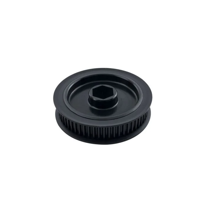
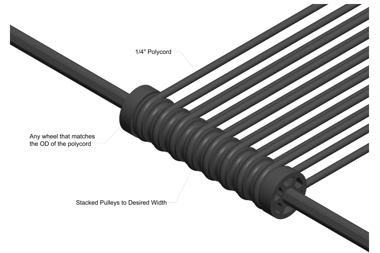
Polycord Belts - Belts that come in a spool and must be fused together. Can have toothless pulleys, and are more used for moving items linearly, such as game pieces in an indexer. Not often seen for power transmissions though.

Math
We do not make vibes-based robots, so there is math and intention behind every power transmission. You should be using Reca.lc, ambcalc.com, or JVN Mechanical Design Calculator on all mechanisms. Find the belt or chain calculator, and input your sprockets or pulleys and center-center distance. This will give you the specific belts you need, or how many chain links you should use. For individual mechanisms, calculate the gear ratio first, then input that into their respective calculators.
Shooter Designs
Projectiles in FRC: A Practical How-To Guide
1) Pick a launcher style (pros/cons & when to use)
-
Hooded flywheel (single/dual wheel): Most common, accurate over a range; add an adjustable hood for multiple shot locations.
-
Good for balls/notes.
-
To achieve backspin on the game piece, use one flywheel.
-
For flat spin and front spin, use two flywheels. Chief Delphi+1
Hooded shooter built by 1678
-
Catapult/puncher (spring/elastic/motor-latched): Great for heavier/softer objects or when you want consistent “set-shot” distances; needs careful energy storage & release sizing.
-
A common mechanism for tension-based launchers is the choo-choo.
-
This works similarly to a train wheel, where a wheel rotates and at a certain point, it will engage a linkage, priming it.
-
It will then rotate and let go of the linkage, releasing energy. Chief Delphi+1


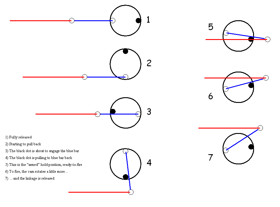
Puncher built by 1114 Choo-Choo mechanism diagram
-
Turret vs. fixed: Turret simplifies driver alignment and allows shooting while driving; a fixed shooter is lighter and simpler.
-
A fixed shooter will use its drivetrain (usually swerve) to aim.
-
Fixed shooters will commonly use a two-plate design.
-
Turret shooters also may have to be zeroed before each match. (See 254’s turreted designs & feeder integration.) Chief Delphi+2media.team254.com+2
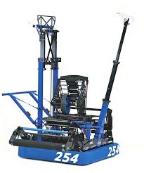
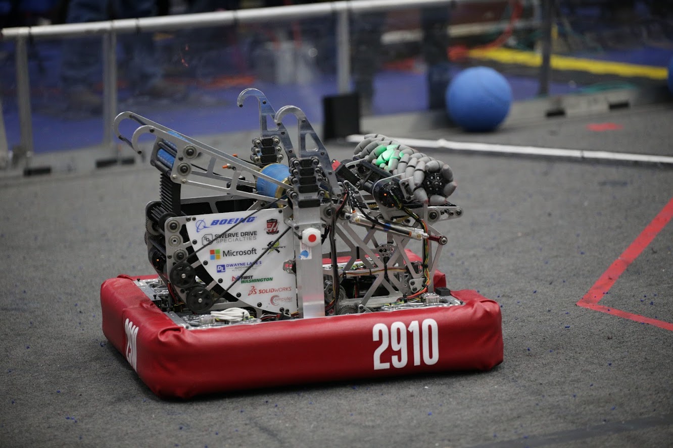
Turret shooter built by 254 Fixed shooter built by 2910
2) Shooter geometry & compression (for hooded flywheels)
Goal: Control contact time and spin so the game piece leaves at a repeatable speed/angle.
How to:
-
Start with compression: Distance from wheel to hood smaller than the game-piece diameter. Typical starting point many teams reported in 2020: ~1.5–2.5 in; tune per game piece. Chief Delphi+1
-
Choose hood material: Polycarbonate is common; grippier liners increase spin if the piece slips on the hood. Chief Delphi
-
Wheel diameter & inertia: Bigger wheels give higher surface speed at the same RPM and generally more energy storage (flywheel effect); trade against weight & packaging. Chief Delphi
-
Adjustable hood: Enables one mechanism to hit multiple distances/angles; CAD your arc so the normal force and compression stay reasonable across angles. Chief Delphi
-
Rear “kicker”/pre-spin roller (optional): Can improve feeding and reduce shot-to-shot variation; prototype to validate. Chief Delphi
3) Motors, gearing, and energy
How to:
-
Pick motor(s) to match your RPM/torque needs (NEOs/Falcons/775pros). Prototype one motor, log RPM recovery, then scale; example community configs exist (e.g., multi-775pro setups). Chief Delphi
-
Gearing: Target a no-load free-speed that’s 10–30% above your on-shot speed to allow headroom for control.
-
Flywheel inertia: Add mass (steel plates or heavy hub) for better velocity hold-up during a shot—balance vs. spin-up time. (See CD compression threads discussing plate “disks”.) Chief Delphi
4) Feeding, centering, and serialization
Why it matters: Consistent entry orientation & speed reduces shot variance.
How to:
-
Center & single-file: Use “serializer” rollers/geometry to turn wide intakes into a single, well-registered stream. (Great example write-ups in 254 tech binders.) media.team254.com+1
-
Metering sensors: Beam breaks/hall sensors before the shooter to time the feed when RPM is on-target.
These sensors are used to track the ball’s location in order to figure out where it is in the robot. They are placed before the shooter to time the feeding of the game pieces into it when the motors operate as predicted. Specifically, when the Rotations Per Minute (RPM) are on-target.
-
Isolation: Use compliant wheels and passive rollers to control the ball and avoid jams before the throat. media.team254.com
- Electrical Isolation: It makes sure that one electrical part doesn't affect another electrical part in the robot.
-
Program Isolation: It makes sure that the sensor only senses the ball. It also keeps the sensor clean so it can read the ball.
-
Mechanical Isolation: It makes sure that the no important parts get damaged from bumps. It keeps parts separate so they don’t damage each other, like making sure the shooter’s screws or edges don’t cut or hurt the ball while shooting or moving and vice versa, by adding like covers, the ball touching a smooth surface, or using soft material.
5) Control: getting repeatable velocity (and fast recovery)
Core strategies you can implement in WPILib:
-
Bang-bang: Simple on/off for hitting setpoint quickly—great baseline. FIRST Robotics Competition Documentation
-
PID/FF velocity control: Use WPILib’s tuning flow; characterize kS/kV/kA, then add PID for disturbance rejection. FIRST Robotics Competition Documentation
-
State-space (advanced): Model-based control for excellent disturbance handling and recovery. WPILib has an end-to-end flywheel walkthrough. FIRST Robotics Competition Documentation
Practical steps:
-
Characterize the shooter (SysId or logged step tests) and compute feedforward. FIRST Robotics Competition Documentation
-
Tune: hit open-loop near the target, then close the loop; verify recovery time between rapid shots. FIRST Robotics Competition Documentation
-
Disable motor-safety for flywheels (keeps them spinning during control loops). FIRST Robotics Competition Documentation
6) Trajectory, spin, and aim
How to:
-
Backspin/topspin: More backspin often stabilizes flight and can help “drop-in” style goals; tune with hood friction and wheel-hood speed ratio. Chief Delphi
-
Distance tables: Build RPM/hood-angle lookup tables per range—collect data at marked distances, interpolate in code.
-
Turret/hood strategy: Decide “fixed hood + turret + velocity” vs. “adjustable hood + fixed shooter” based on game tasks and protected zones. (Notes from Spectrum & 2024 meta.) Chief Delphi
7) Catapults & punchers (elastic or motor-latched)
How to:
-
Pick energy storage: Surgical tubing, gas springs, torsion springs; estimate spring rate and energy (½ k x²). Old but useful CD references give ballpark tubing rates—always validate on a test rig. Chief Delphi
-
Size the actuator/gearbox: Use a simple simulation or spreadsheet to match wind-up torque, angular speed, and release angle (see “Electric Catapult Design & Optimization”). Chief Delphi
-
Latch & release: Robust hard latches or dog clutches; ensure pre-load can’t self-release and add physical hard-stops.
-
Cycle time: Design for safe reset under defense (ratchets or worm-gear holds).
8) Prototyping plan (fast & reliable)
How to:
-
Bench rigs first: 2×4 frame, adjustable hood arc, sliding wheel-to-hood distance. Swap wheels/materials quickly.
-
Log everything: RPM before/after shot, time-to-recover, ball exit speed (phone high-fps), hit rate vs. distance.
-
Parameter sweeps: Try compression steps (e.g., +0.25 in), wheel durometer, hood liners, release angles—record a matrix.
-
Durability checks: Shoot 100+ cycles and re-measure your “dialed” values to see drift (wheel wear, liner glazing).
Resources with examples & prototyping ideas: Spectrum resources hub and build blogs. spectrum3847.org+1
9) Software integration: from sensor to shot
How to:
-
Sensor suite: Encoder on flywheel; beam break at exit; gyro/odometry for range estimate; (optionally) vision for pose/aim assist.
-
Shot gating: Only feed when
abs(vel - setpoint) < tolerancefor N ms. -
Auto-aim options: Turret PID to vision target or odometry-based “dead-reckon” with distance→RPM/angle tables. (WPILib control tutorials cover tradeoffs.) FIRST Robotics Competition Documentation
10) Mechanical details that matter
-
Stiff mounting: Shooter & hood need rigidity (avoid deflection changing aim). Elite teams detail robust interfaces between turret and shooter. Chief Delphi
-
Ball path sealing: Close gaps so you don’t lose pressure/energy.
-
Serviceability: Quick-change wheels/liners; access panels for cleaning debris.
-
Safety: Shields around flywheels; never stand in plane of the wheel; interlocks for test mode.
11) Strategy fit & on-field use
How to:
-
Decide shot families you’ll own (e.g., protected zone, “subwoofer,” mid-field). 2024 takeaways: multi-location shooting boosts cycle flexibility but increases complexity—picking one or two money shots can still be very effective. Chief Delphi
-
Warm-up & calibration: Spin up on enable; auto-zero hood; shoot a short drill to confirm RPM table after field reset.
-
Maintenance: Re-index compression (liners wear), check set screws, re-true wheels weekly.
12) Build-season checklist
-
Define target ranges/angles and cycle goals (with strategy).
-
Select launcher type; CAD the geometry (arc, compression, packaging).
-
Prototype quickly; collect a data table and pick initial control strategy.
-
Integrate a reliable feed path with sensors.
-
Lock in materials, fasteners, guards.
-
Code gating & recovery; validate with drill cards (e.g., 10 rapid shots at 2 ranges).
-
Create pit procedures for inspection, alignment, and upkeep.
Suggested “Further Reading” blocks for your wiki
-
WPILib: Tuning a flywheel, state-space flywheel control, strategy choice. FIRST Robotics Competition Documentation+2FIRST Robotics Competition Documentation+2
-
Spectrum 3847 resources and build blogs (design slide decks, prototyping ideas). spectrum3847.org+1
-
ChiefDelphi canonical threads on hood geometry, compression & materials. Chief Delphi+3Chief Delphi+3Chief Delphi+3
-
Catapult math & examples. Chief Delphi+2Chief Delphi+2
-
Elite team tech binders for feeder/serializer & turret integration. media.team254.com+2media.team254.com+2
Intakes and Linkages
4 Bar Linkages:
4 Bar linkages use 4 bars(crazy, I know), 2 on each side of the bot, and dead axles instead of hex bars with bearings to pivot. These dead axles don't use bearings, making them a lot more reliable and strong than a hex bar. They are traditionally powered by pistons, but we want to use motors now because of our sweet sweet WCP parts. The 4-bar linkage also has a smaller footprint than a pivoting hex or SplineXL intake and can be good for games requiring a large shooter tower and over-bumper intake at the same time(see Aurora from 2022). They are often harder to make than traditional intakes, but have great benefits like discussed above, which is why we are teaching it.
TL;DR
Pros:
- Less prone to breaking than hex-bar
- Can take up less space if made well
Cons:
- Time consuming to make and somewhat harder to CAD than simpler ones
- Mostly needs pneumatics, more complex with motors(which we want to use because of our WCP sponsorship)
Image above is 1678 2022 Rapid React Intake
How to make a 4 bar Intake:
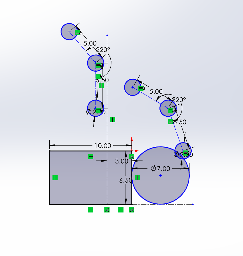
1. Create your base Geometry, this includes a rectangle for your robot body, small circles for your rollers(these will generally be the only hex-bearing parts of your intake), and a larger ball that is your game piece and determines the size and position of the smaller wheels.
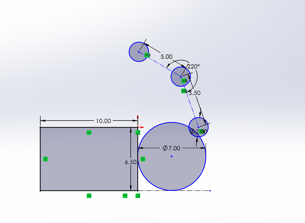
2. Create a line marking where the bumper ends, and copy your geometry past the line. This second geometry represents the rollers in the stowed position, and should keep the small roller circles in the same orientation relative to each other.
3. Create 2 circles linked up to the same two points on the Geometry (Make sure to lock your Geo in place). These will allow for you to test your stowing motion.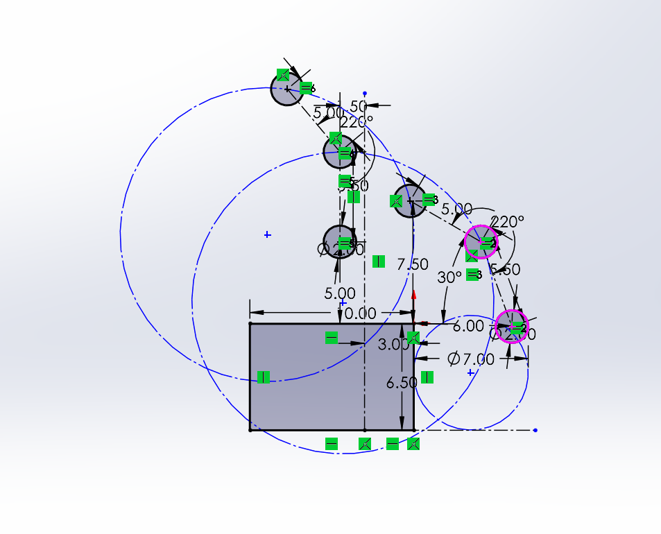
4. Mess with your circles to make them fit.
Criteria for Circles:
- Centerpoint must be behind the bumper lines
- Try not to make them too low on the robot
- Try to keep the circles similar size
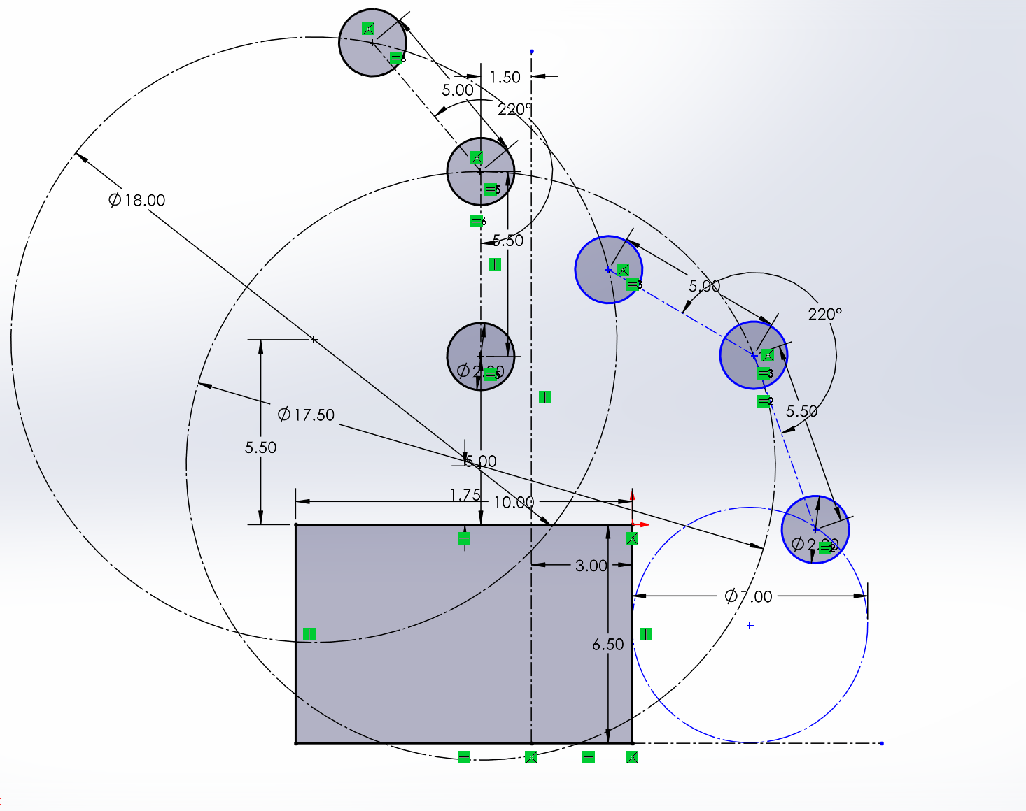
5. Dimension the Circles and their position. *At this point you can remove the bottom Geo's connections and move it around :)
6. Add Lines and Liven it up (Add bearing holes, Slots ect.)
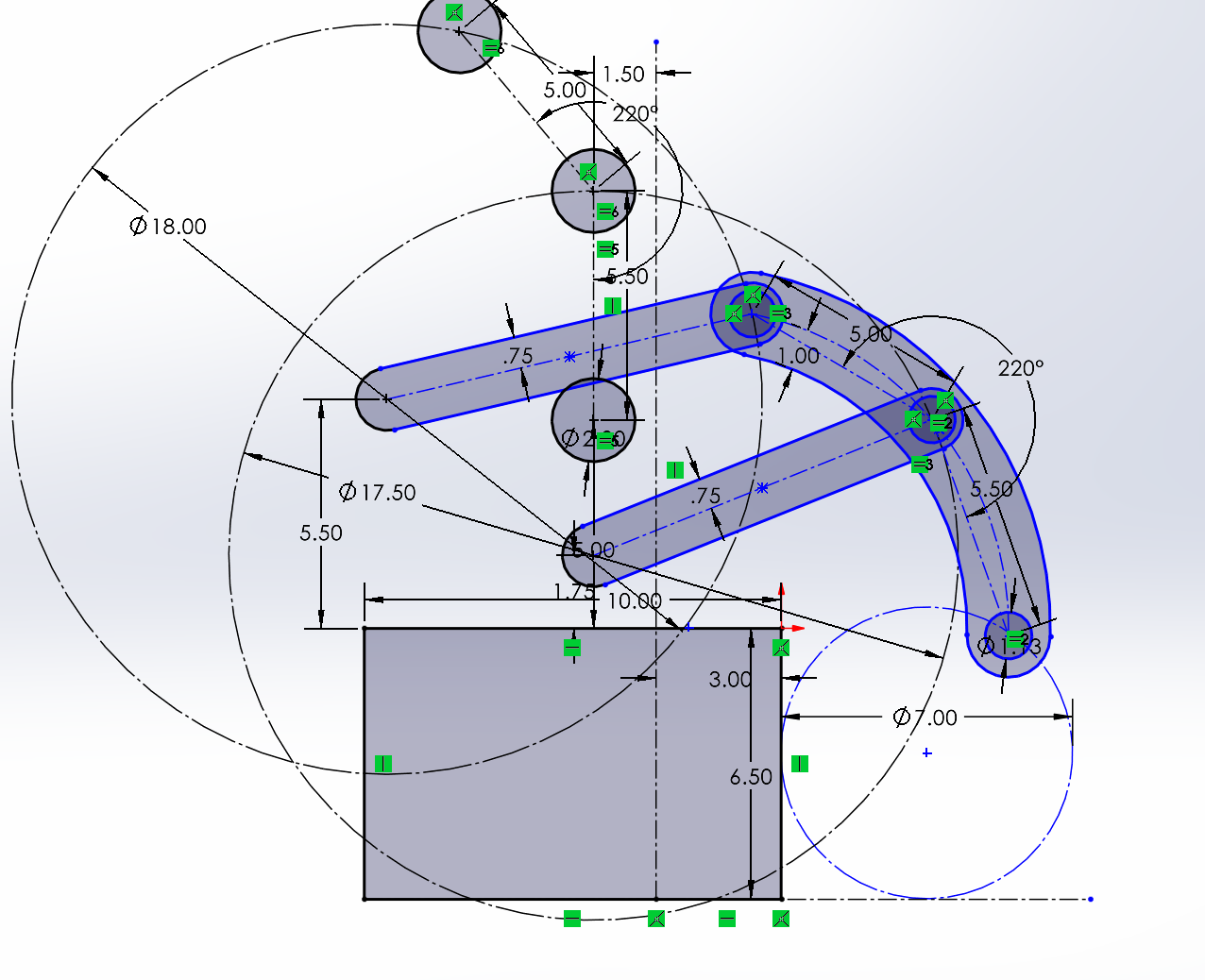
7. Finished; now that your geometry is done, do the fun parts. Make the slots into separate parts that can be used as pivots, get your bearing and dead axle holes in the right sizes, and make your rollers. Then just link up your motor or piston and you're done! Mirror it onto the other side, position your roller wheels and the assembly onto your bot, and congratulations, you've just finished your first 4-bar dead axle intake :D