Crimping
Practices
Use a “Goldilocks Approach”
Too much exposed copper can lead to short-circuiting
Not enough creates a weak connection and can come out at the worst time
Have someone else pull-test your connections after you have crimped a wire (cross-check)
Anderson Crimp
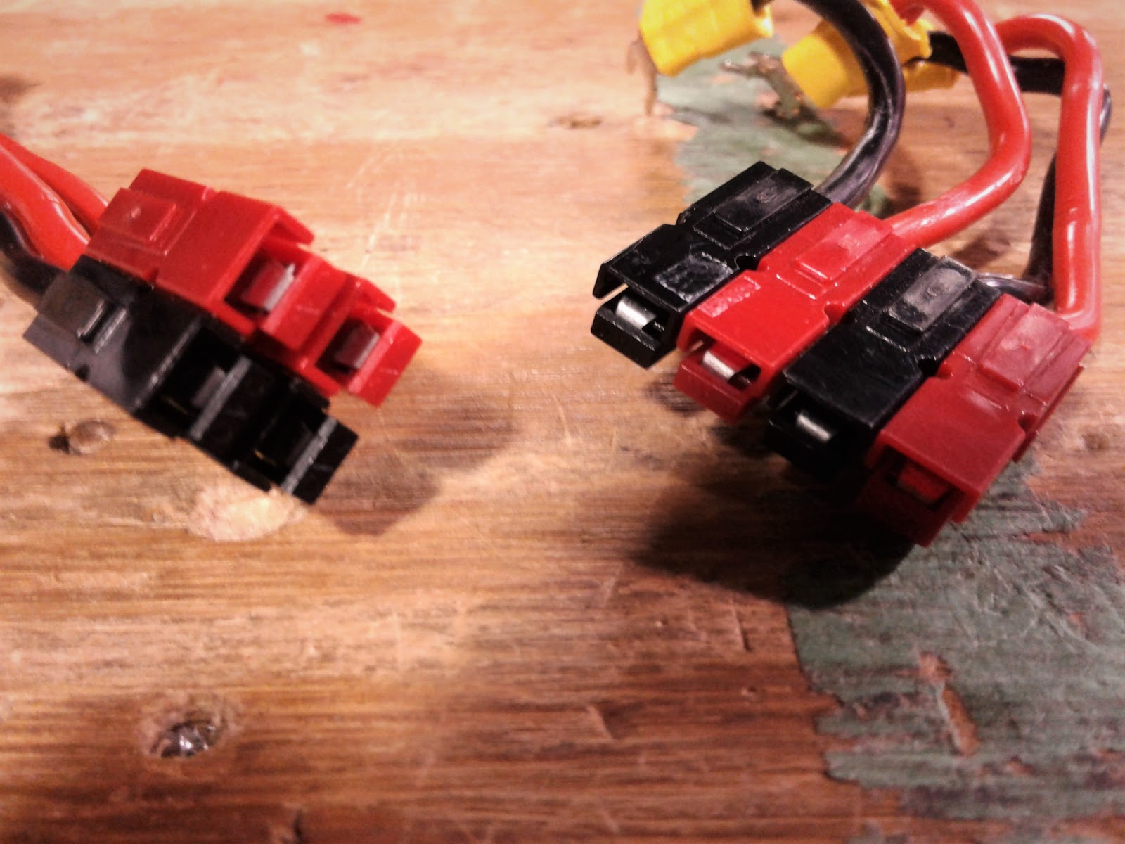
Anderson/Powerpole Connectors
Great for anything that inputs/outputs power on the robot 10-20 AWG
(Powerpole Starter Kit - AndyMark, Inc)
The first step in crimping and creating Anderson connections is to strip the wire of its insulation.

We typically use this wire stripper on the correct section for the specific Anderson gauge.
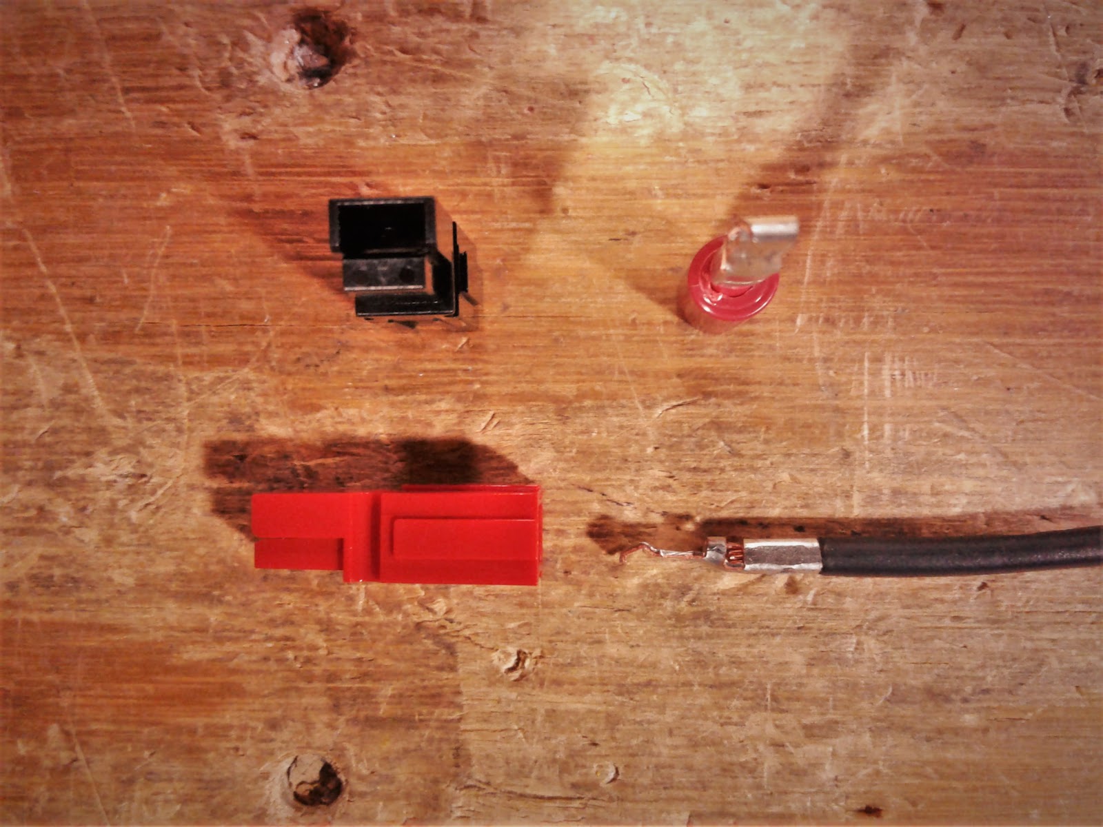
Once the wire is stripped, you want to prepare your Anderson crimp for the copper conductor.
It should be something like this:
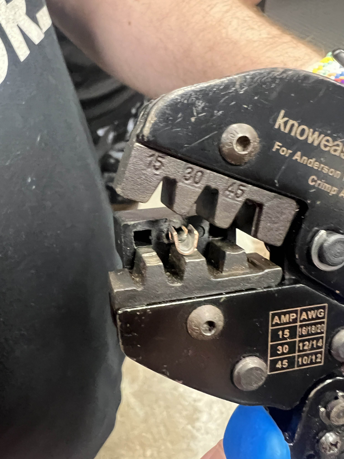
From there, you want to take your Anderson wire crimper and put it into the middle setting (30).

Note: Our team has used mainly the middle setting for our wiring, though we have noticed less durability past 22 AWG
In assist to your crimping of Anderson crimps, some electrical students on our team have adopted the method of “prefiring” which includes putting the crimp inside the crimper and then inserting the wire. Any method of crimping is fine as long as the wire is completely inside the crimp, the crimp does not have any insulation inside, and the crimp is inside the crimper during the time of connection.
“Prefiring”:
Note: Prefiring is a method that can execute poorly if misaligned, be sure to use what is comfortable but effective for you
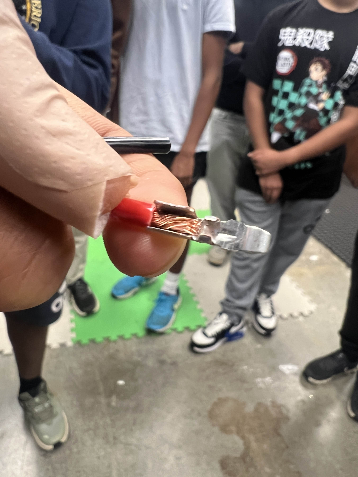
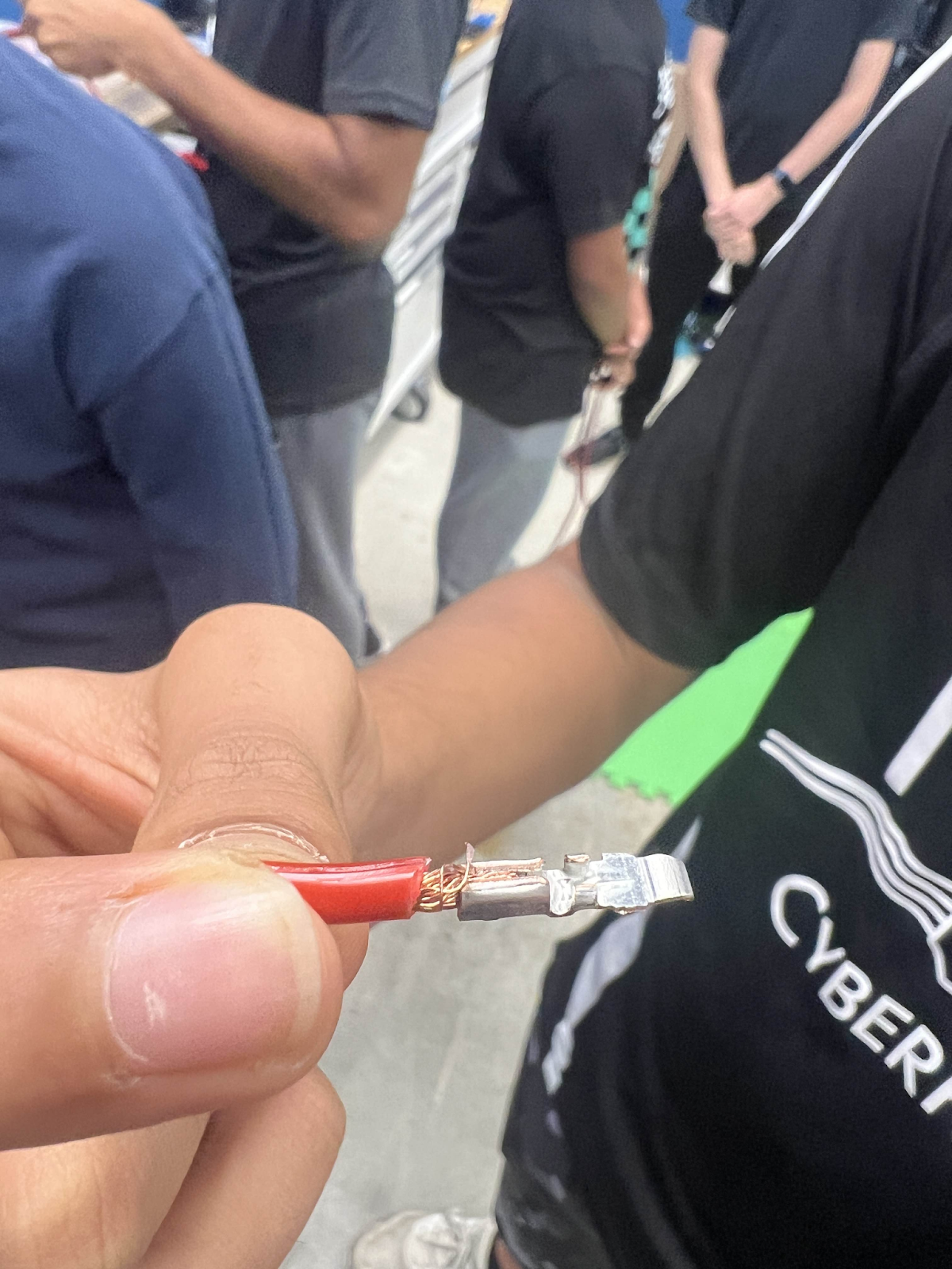
Regardless of method chosen for Anderson crimping, your wire should look like this:
From there, you move onto putting the crimp into housing!
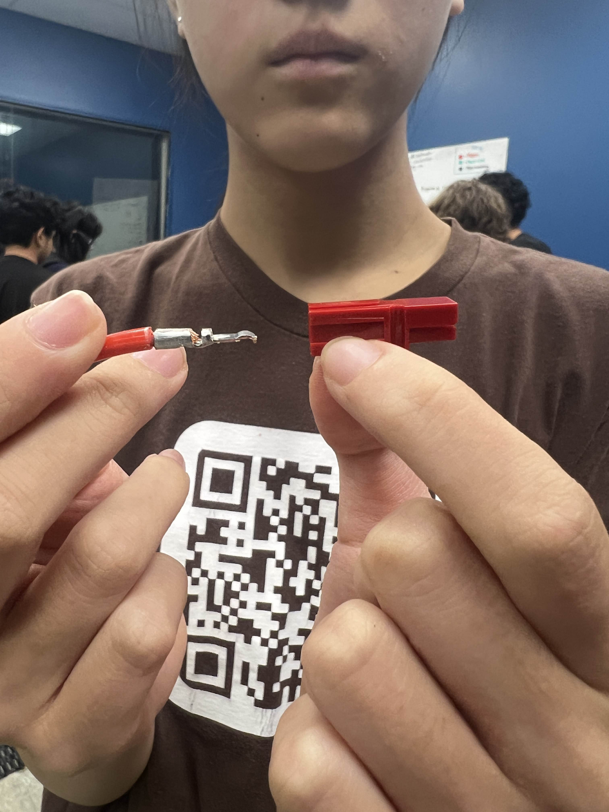
Make sure that your crimp is going inside the housing to look something like this and at this orientation.
From there, push into the housing and you should here a little *pop*
Afterwards, be sure to have someone pull test your connection.
Finished result:
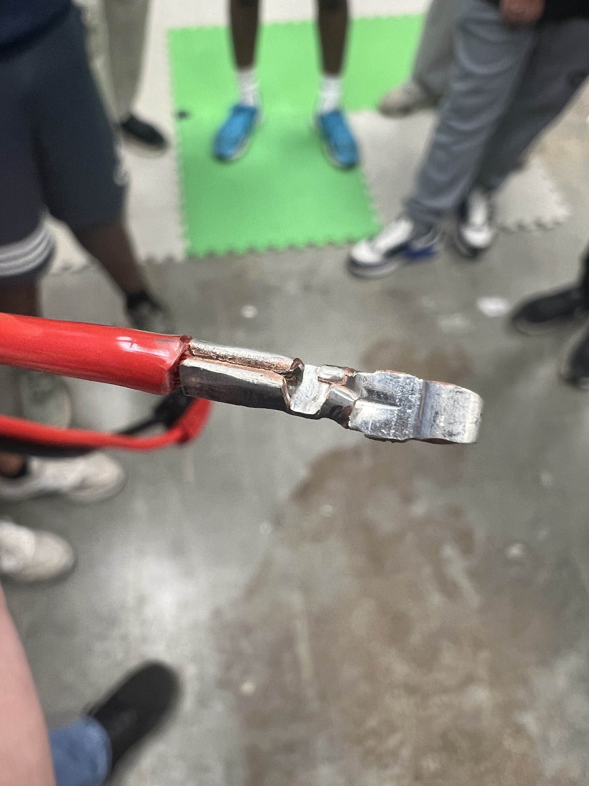
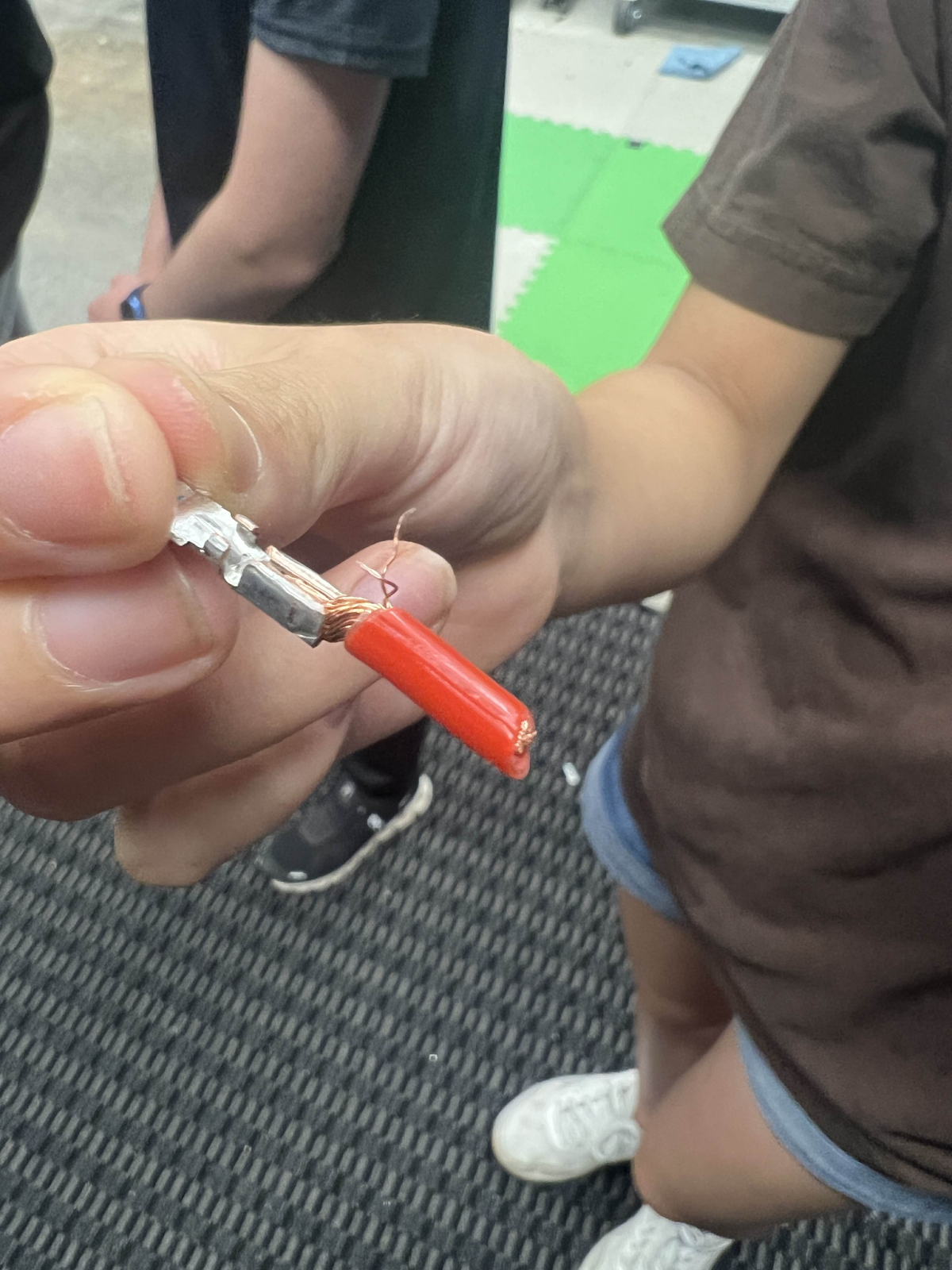
What NOT to do:
Strand of wire out everywhere, crimp is not encapsulating all the wire strands
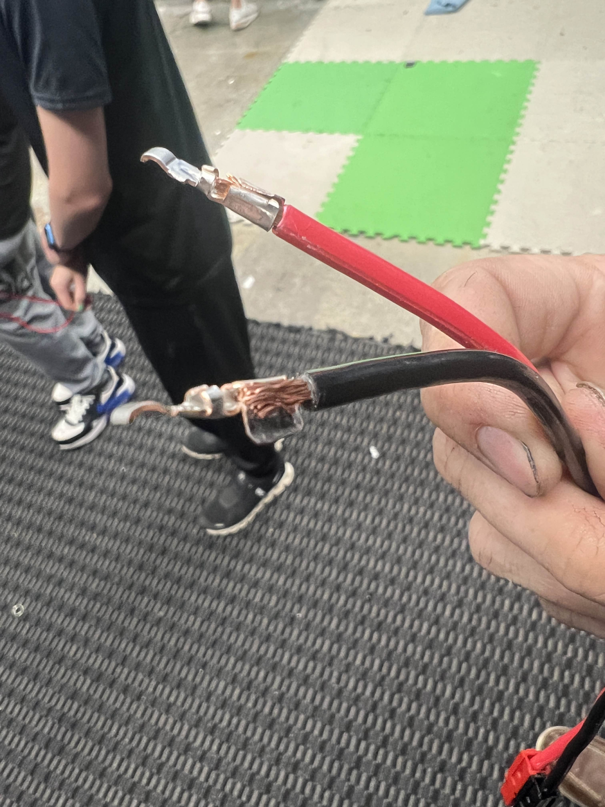
Crimp flag is way out leaving wire exposed and a bad connection.
AVOID LEAVING WIRE EXPOSED AND POOR CONNECTIONS TO THE CRIMP
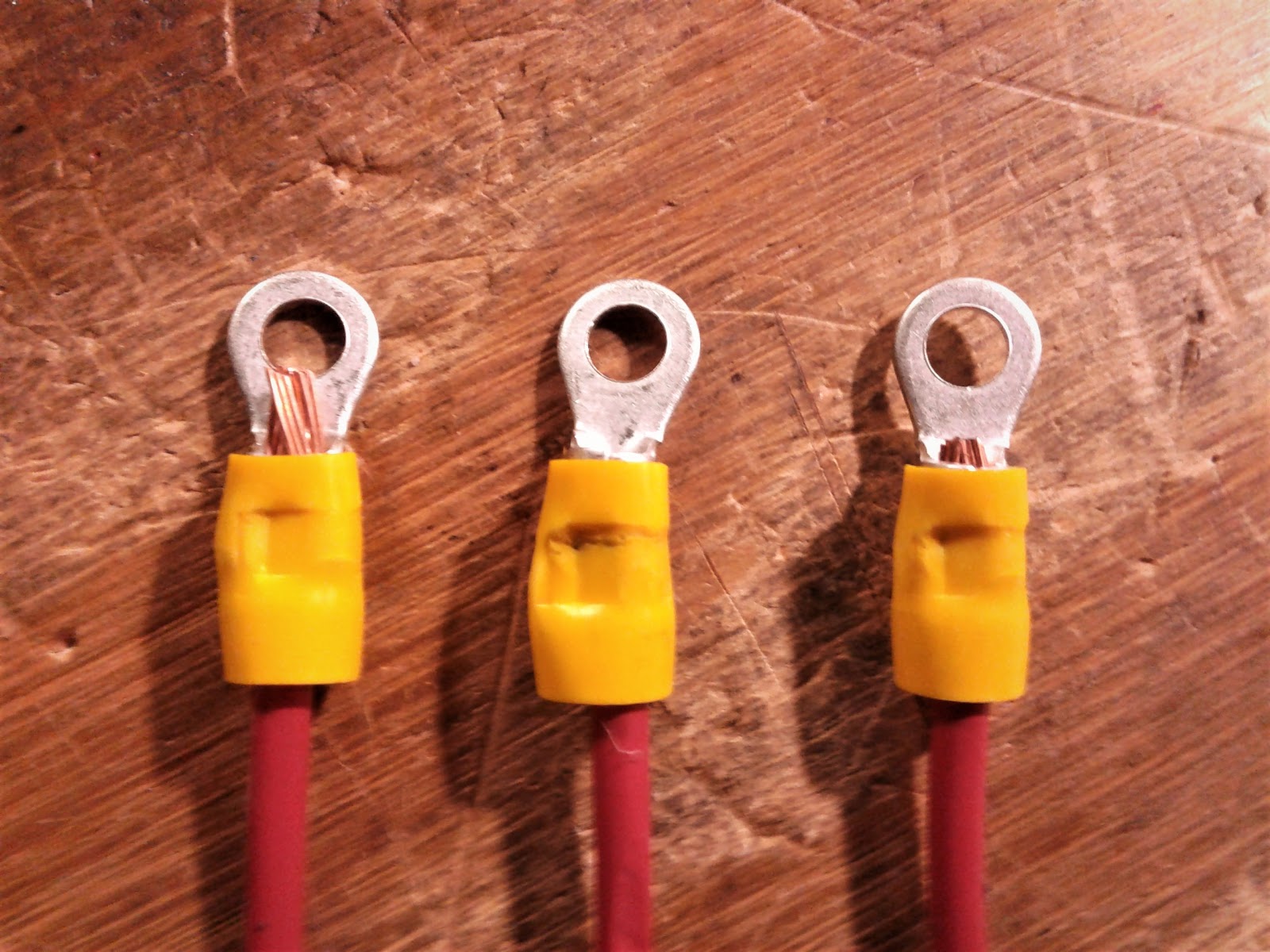
Ferrule Crimps
Context:
We use these materials:
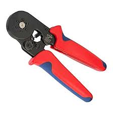
Ferrule Crimper

Wire Stripper
We use blue ferrules for 22-gauge wire
Ferrule crimps are probably the easiest crimps you can do on the robot. However, learning how to do them the right way is essential.
STEP 1:
Strip your wire -
You want to strip your wire so that it is around the length of the conductor on the ferrule being used (usually pretty long).
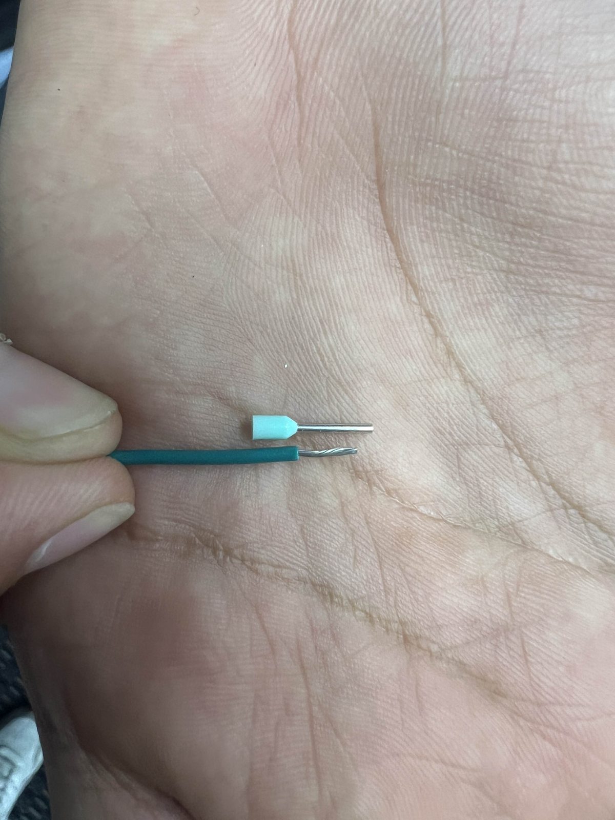
You should be looking at something like this
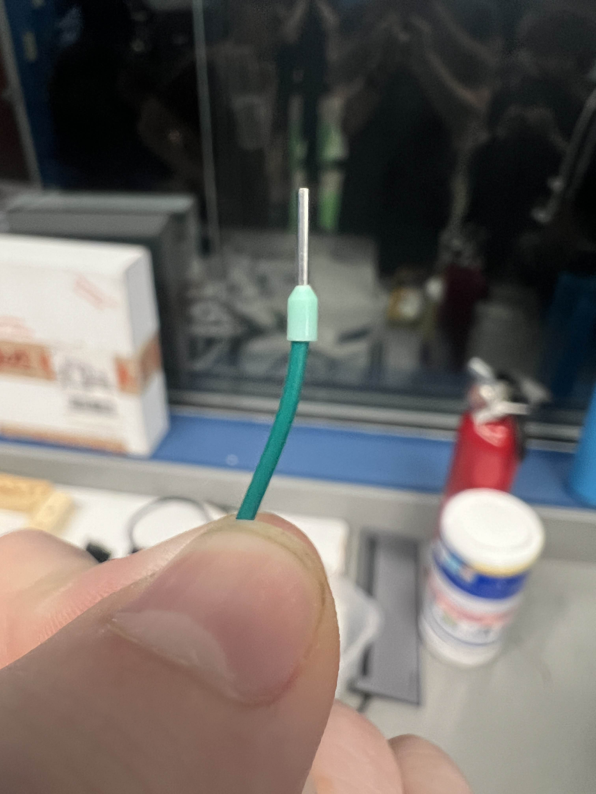
STEP 2:
From there you want to insert the wire into the ferrule crimp and try and make sure that the wire goes up high into the conductor (excess can be cut-off).
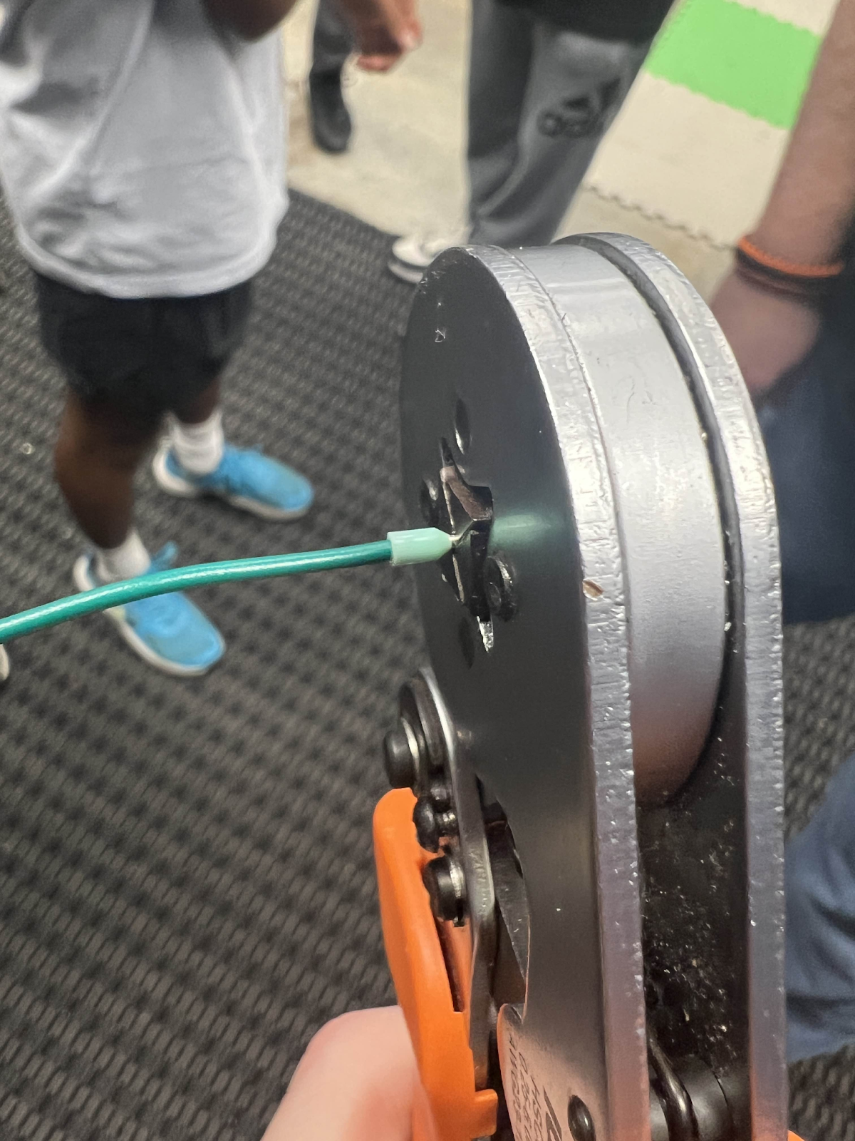
STEP 3:
After this you want to take your ferrule crimper to begin crimping!
When crimping ferrules, make sure that the conductor is the only thing inside the crimper and DO NOT crimp the insulation.
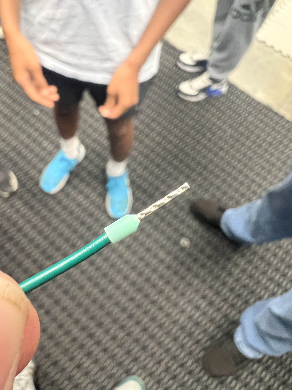
Finally, when done, your crimp should look like this:
Molex Crimps
Molex is the brand of crimps that we use in ensuring connection between 22 gauge wires.
This has been a challenge for some of our electrical students to mastering it is important for our robots power and CANbus.
The first step in crimping these includes stripping the wire. You want to strip only a little off the wire because you will be crimping this inside the Molex. Less than half an inch is a good amount for this.
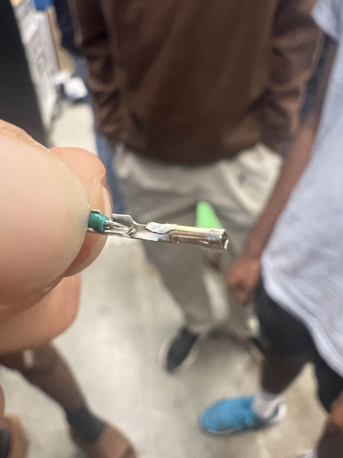
From there you want to take out a Molex Crimp
Note: for this wiki post, we will be showing the crimp process for a female crimp. The process for the male Molex crimp is identical and follows the same format and procedures.
From here, you want to adjust the molex crimp onto the stripped wire so that the “bottom” flap is on the insulation part of the wire and the “top” flap is on the copper wire. Make sure that you are not including too much insulation for the bottom flap and you want to be closer to the edge of the insulation.
This is a side view:
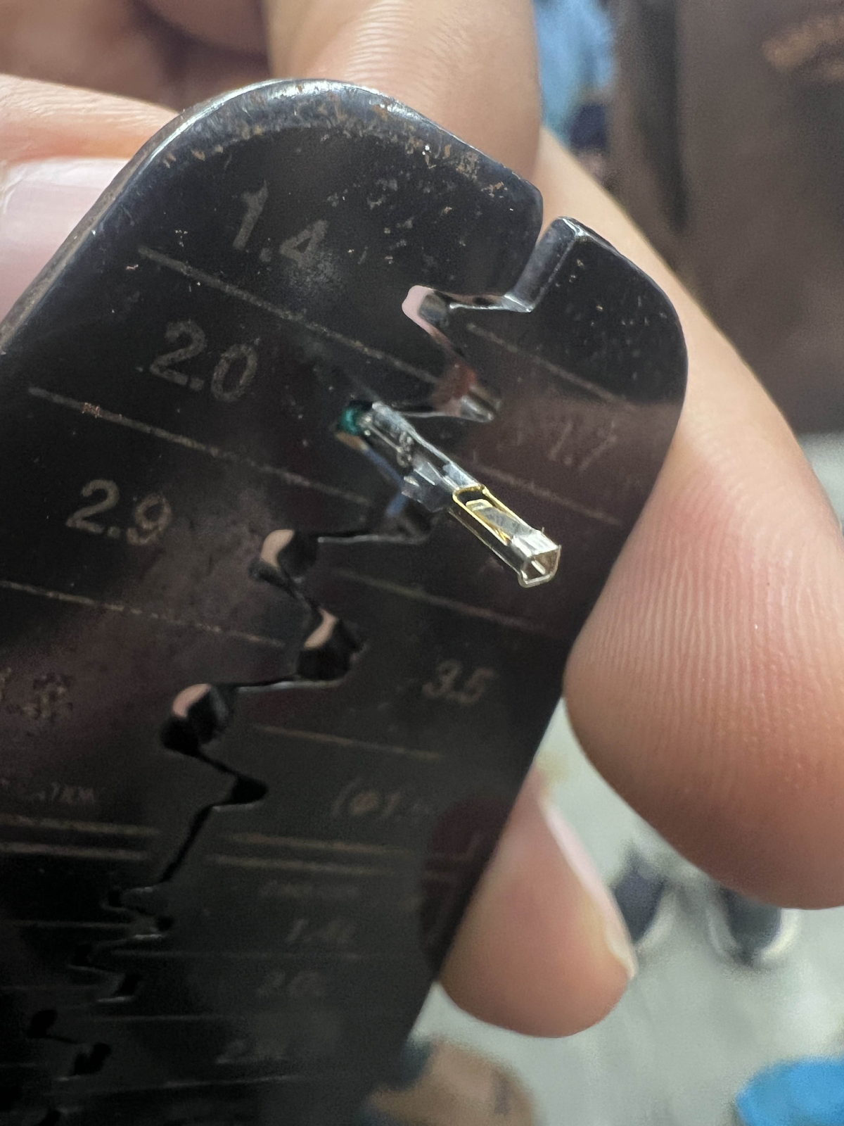
From there you are ready to begin crimping.
Take your crimp on the top flap to the side of the wire crimper that is labeled as “Conductor” and use the 1.7 Ridge in order to press down on the flap.
It should look similar to this:
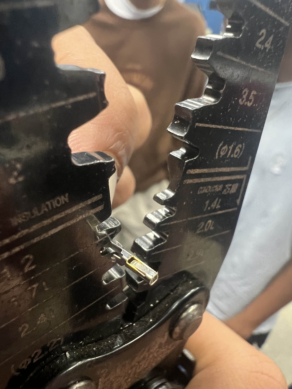
Take your crimp on the bottom flap to the side of the wire crimper that is labeled “Insulation”
You will use the 2.0 Ridge in order to press down this flap.
It should look similar to this:
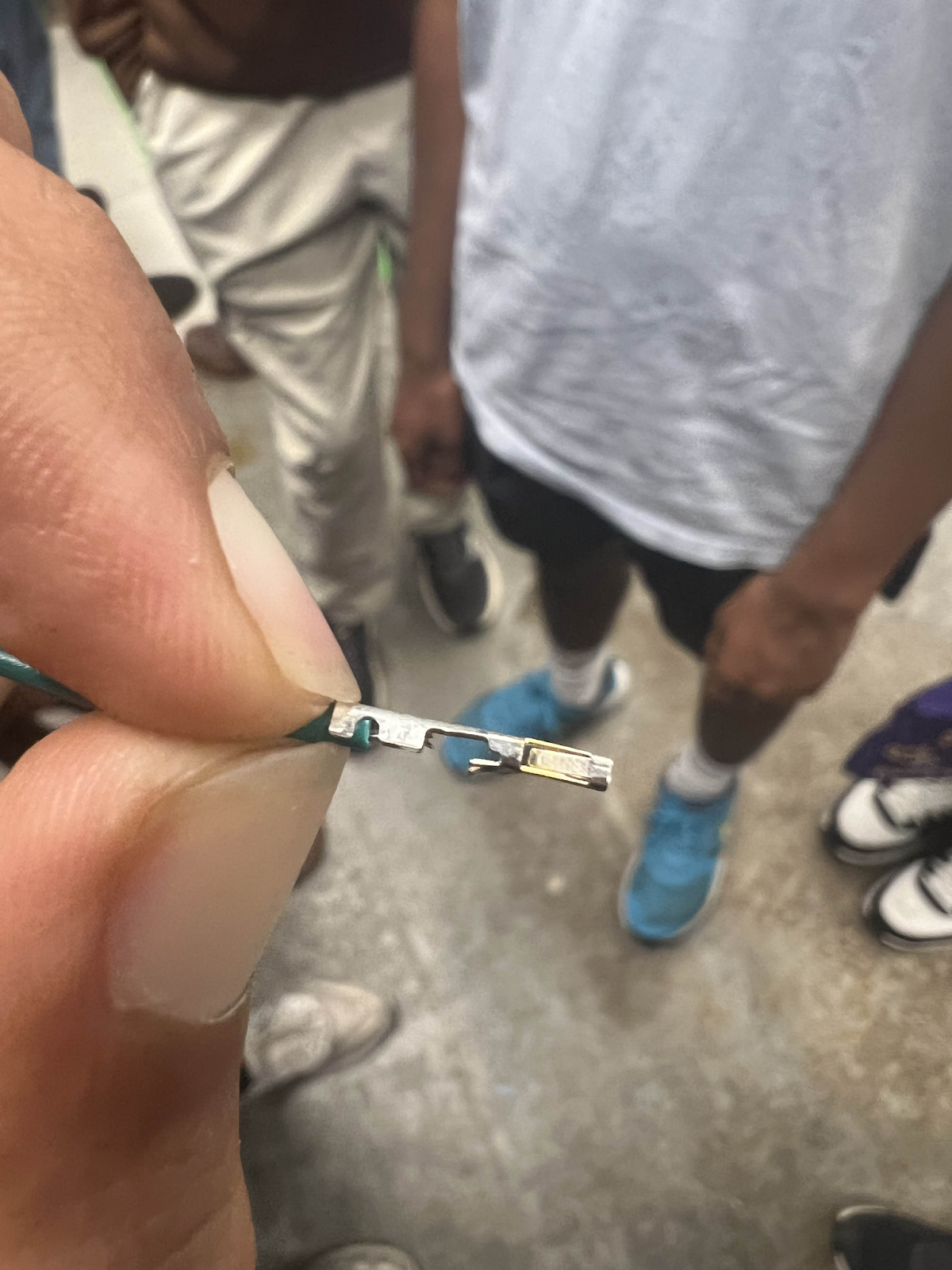
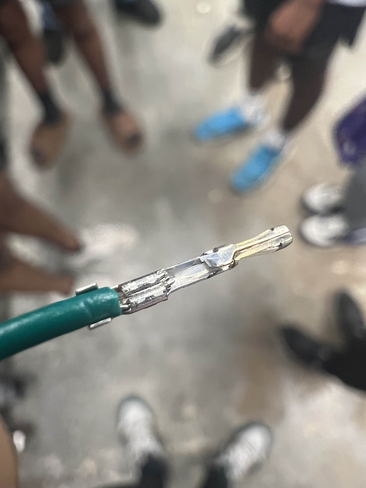
Your finished crimp should look like this:
Finally, to assemble your crimps into the housing.
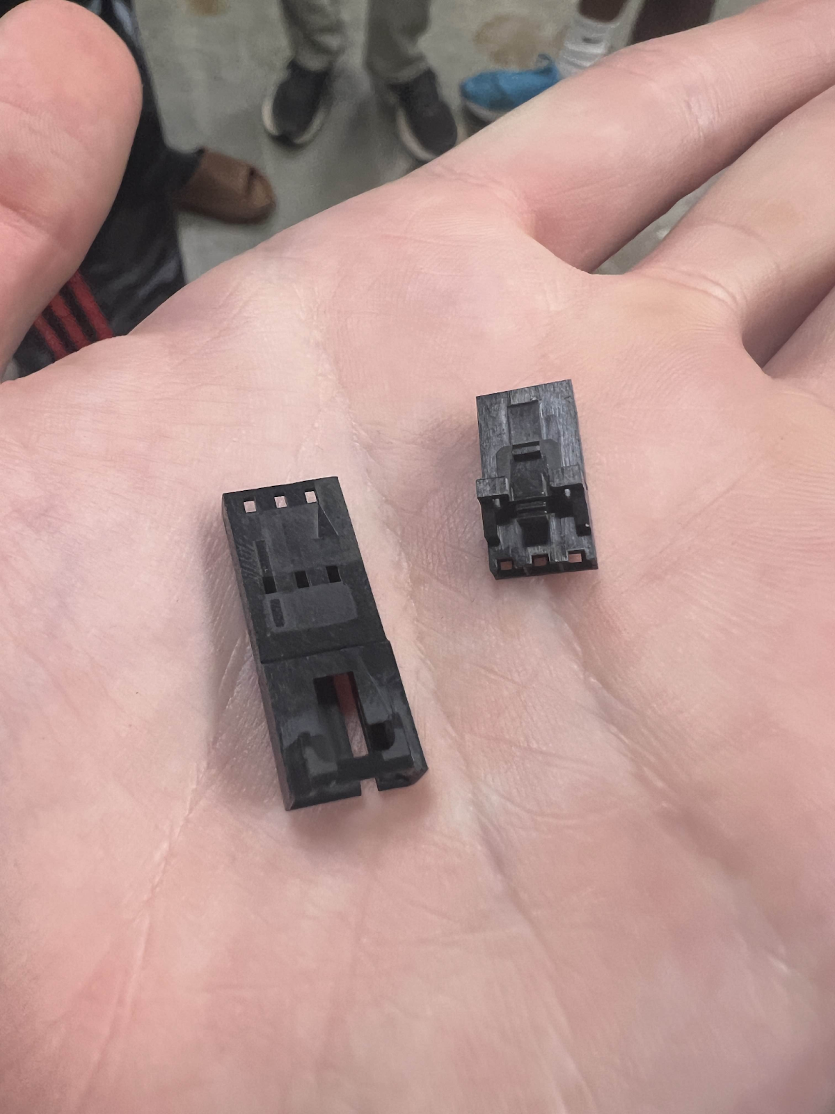
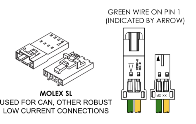
The housing on the left is for Male Molex Crimps whilst the right is for Female Molex Crimps
For standard FRC control system wiring, the black and red wires represent ground and power whilst the green and yellow wires represent CAN or Controller Area Network.
A rule that, as Mukesh quotes it is, “The darker color goes onto the arrow while the lighter color is on the opposite side”
To decipher this quote, it basically is a rule used to show where the different wires go in a housing.
For a 22-gauge power wire, the black (ground) wire is on the arrow while the red (power) wire is on the opposite side
For CAN, the green wire is on the arrow while the yellow is on the opposite side.
This is important as any changes in this can result in errors in either CAN or power.
Remember that red (power) is positive, meaning that it sends out power while black (ground) returns the path and completes the circuit. Mistakes in consistency can result in bad errors.
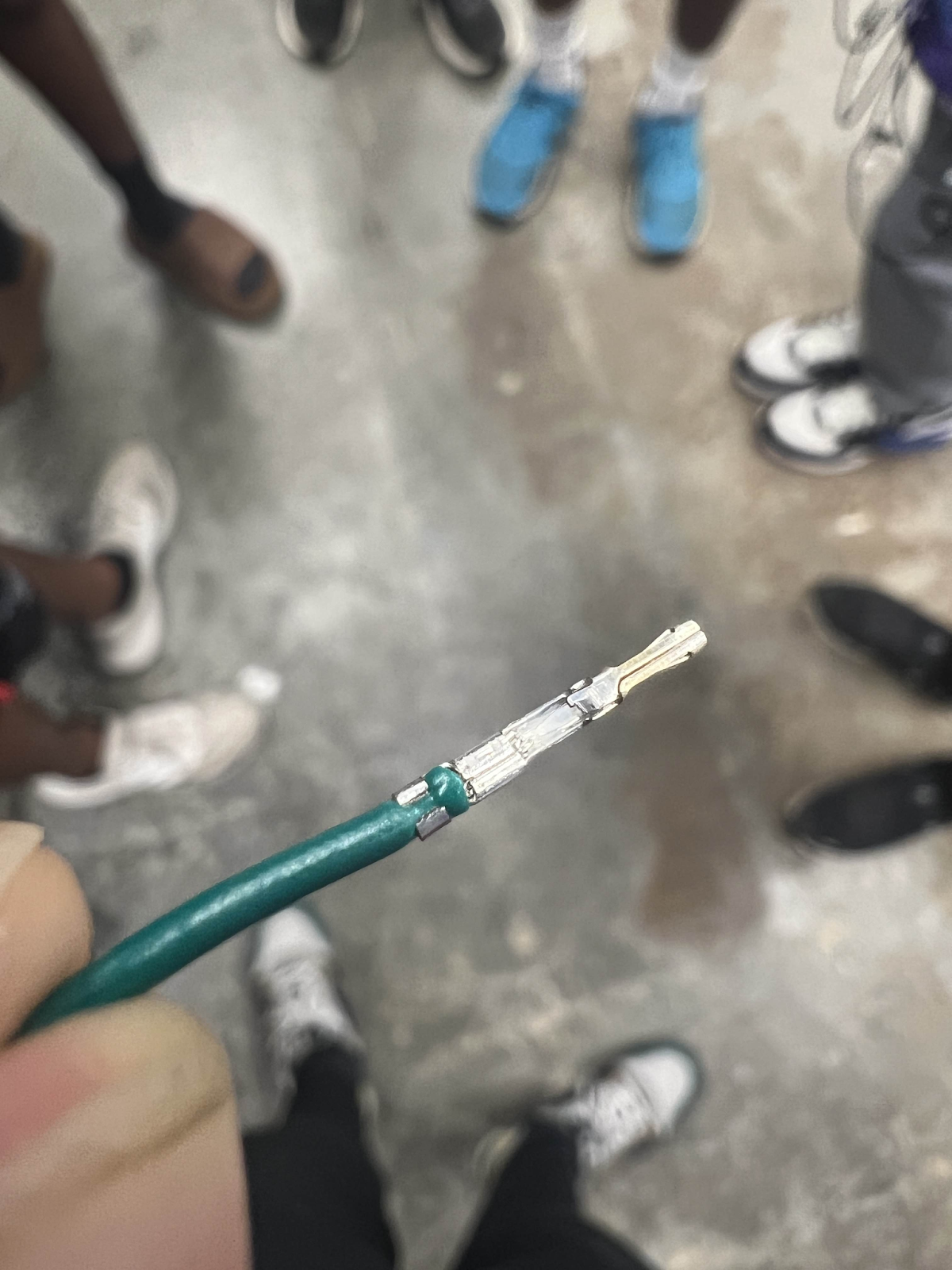
On your crimps, there is a little flap that sticks out of the crimp:
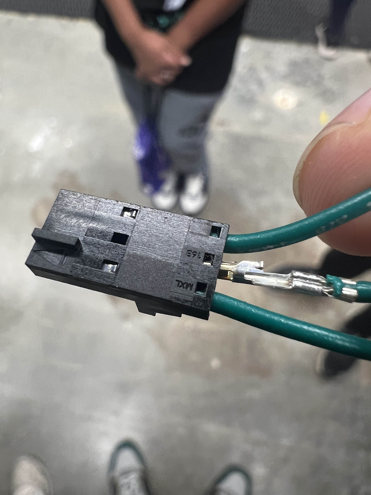
This is what connects to the housing.
Be sure that when you stick a crimp to the housing, the flap is going up the side with the hole to make sure the crimp is the right orientation and locks.
As always, be sure to pull test and have someone else pull test.
Use this for quick reference to an ideal crimp:

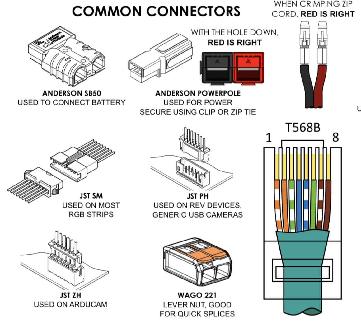
Common Connectors