Electrical
Everything you need to know to be on YETI 3506's Electrical Subteam.
Understand that this book is everchanging so always cross-reference your information!
- What is Electrical?
- The Layout of Electrical
- Wiring
- Wire Management
- Crimping
- Batteries
- Pneumatics
- Electrical Documentation
- Documentation Standard
- Electrical Template for Documentation
- Resources for Draw.io
- Example Documentation from Other Teams
- Creating Electrical Documentation
- Starting your Documentation: Overall Drivetrain Layout
- Detailing your Documentation: Adding Main Components
- Tips for Pit Crew and Competition
- Basic Terminology
- Resources/References
- Resources
- The Most Important Pieces of Electrical Documentation
- Commonly Ordered Electrical Parts for Reference
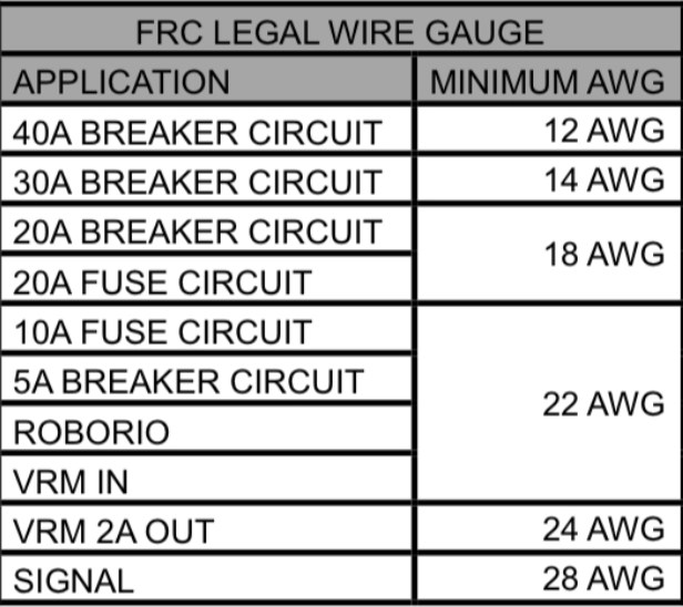
- FRC Wire Gauge Easy Reference
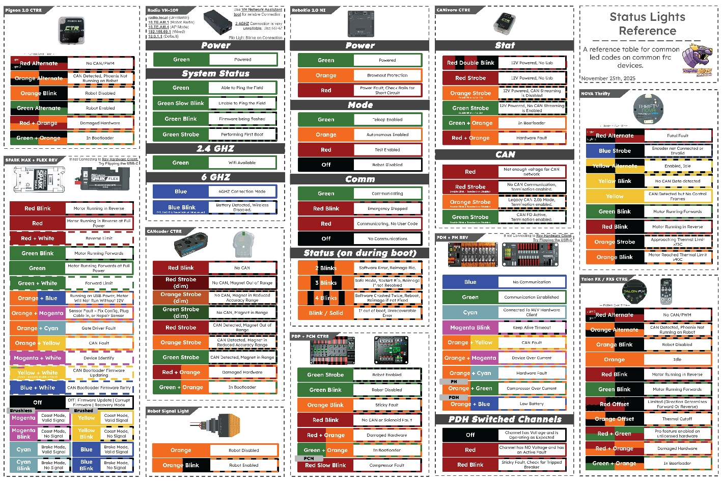
- Status Lights
- Cadathon - Electrical Guidelines
- WCP Kraken Motors
What is Electrical?
Learn about the Electrical Subteam and its responsibilities!
The Electrical Subteam
Electrical is an essential subteam to any robotics team. Planning and wiring the robot is pivotal to a successful and connected competition robot.
Here’s how I think of it:
Programming acts as the CNS (Central Nervous System) that controls and processes information
Mechanical acts as the structure and muscles of the body that provide and perform the actions that the brain wants
Electrical, while usually overlooked, is the PNS (Peripheral Nervous System) that connects the body to its brain.
Safety Practices:
Power off before doing any electrical work (no shocky shocky ⚡)
Finish what you start
Always check for exposed conductors
Battery:
Check wires and breaker, make sure the robot is ready to be turned on.
Try and get a battery that is Good 130
Etiquette:
Once power is involved, don’t do anything you’re not sure of, and be sure to ask questions
No mistake is a singular person’s fault, we are a team!
If you are bored, do not play with the tools on the table (please!)
The Layout of Electrical
What does the electrical layout look like?
Important Information
This is the fun stuff.
Here is a basic FRC Electrical Subsystem:
Some of the basic components of the electrical subsystem include:
-
12V Lead Acid Battery
-
Nominal Voltage: 12V
-
Capable of over 180 amps
-
120 Amp Breaker
-
Used to disconnect and connect the battery and prevent the system from drawing too much power.
-
PDH (with its breaker limits)
-
Distributes power from the battery to all components plugged into it
-
Breaker limits current to the component. ( 5 amp - 40 amp options)
-
The mini-fuse is not resettable ( 5 - 20 amps)
-
VRM (Voltage Regulator Module)
-
Regulates the voltage directed from PDH to smaller devices
(limelight, etc)
-
RPM (Radio Power Module)
-
Supplies PoE (Power over Ethernet) for the radio.
-
Radio
-
Communicates with the driver’s station via its WiFi network
-
Connects to VRM for power and Roborio for Ethernet
-
Robo Rio
-
Essentially the brain
-
Any device that needs info must be connected here. Different ports help different devices and their needs
-
RSL
-
Controlled by the RoboRIO
-
Flashes whenever the robot is enabled
-
Stays solid when disabled.
-
CANivore
-
Separates different CAN bus chains.
-
Ex. one for drive and one for upper shooter
-
CANcoder
-
Precisely measures the rotation of a shaft or wheel
-
Integrated within CAN chain
Follow these radio status lights:

LED Status Indications | FIRST FRC Radio
There are different sensors on the robot that can be used in code in order to detect something.
Analog Signals
Smoothly and continuously go through a range of values
Accelerometers create analog signals
Digital Signals
Blocky and steps between two values, 1 or 0
Limit switches create digital signals
Different sensors include
Limelights- A smart camera that makes giving the robot vision simpler. Used for April tag or retro reflective tape detection for targeting scoring elements.
The Pigeon - What angle the robot is at on the X, Y, Z axes. Critical for autonomous or balancing. Able to tell how fast the robot is moving. Tells us exactly what orientation and speed the robot is going.
Encoders- Absolute and incremental. Both types are used to measure the rotation of an axle. Absolute encoders know their angle on startup, while Incremental encoders need to be zeroed
Limit Switch and Mag switches-
Lim: Hitting the top button interrupts or starts the flow of electricity, depending on how it’s wired. Good for hard limits.
Mag: Detects when a magnet is close to the sensor, good for when you don't want something physically touching
Beam Brakes and CANandCOLORs- Uses light to tell if there is an object between the emitter and receiver. Tells how far away an object is by bouncing light off it and recording the time it takes to sense the light. CANandCOLORs measure heat, distance, color, and more!
Linear and Rotary Potentiometers- Uses a change in resistance as the shaft rotates or the slider moves to indicate position or adjust voltage levels
Sensor Types:
-
Rotation
-
Mag Encoders
-
Limit
-
Magnetic/Hall Effect
-
Visual
-
Color
-
Proxy
-
Limelights
Wiring
How to Wire Different Components and Sensors
The Wiring Process
Throughout our subteam, we use a variety of wires that accomplish different things. The color and size of wires are very important and something that we need to pay attention to.
The CAN wire on our robot is the 22-gauge green and yellow wire.
It connects all of our
-
Motors
-
Encoders
-
RoboRio
-
Pigeon
-
CANivore
-
CANdle
-
PDH
Essentially, it connects everything that needs some sort of information
Pulse Width Modulation (PWN):
-
22 gauge
-
Red - Positive
-
Black- Negative
-
White - Neutral/Signal
Power
-
Usually a lower gauge wire (meaning greater thickness)
-
10
-
12
-
14
-
Crimped with Anderson crimps
-
Connects components to power suppliers (PDH, VRM, etc)
Battery Wire
-
4 or 6-Gauge Wire
-
Special Anderson and crimping system
-
Connect to Batteries
Status Lights
If you are ever unsure about the condition of a device, always reference its Status Lights and/or Phoenix Tuner
For a quick reference on status lights for most electrical devices on an FRC Competition Robot, look at this: Status Light Quick Reference — FIRST Robotics Competition documentation
Phoenix Tuner is a way for a user to reference and control a device. From there, you can update its firmware and use it to test prototypes easily.
Please reference this for Phoenix Tuner: Phoenix Tuner X and its installation, Installing Phoenix 6 (FRC)
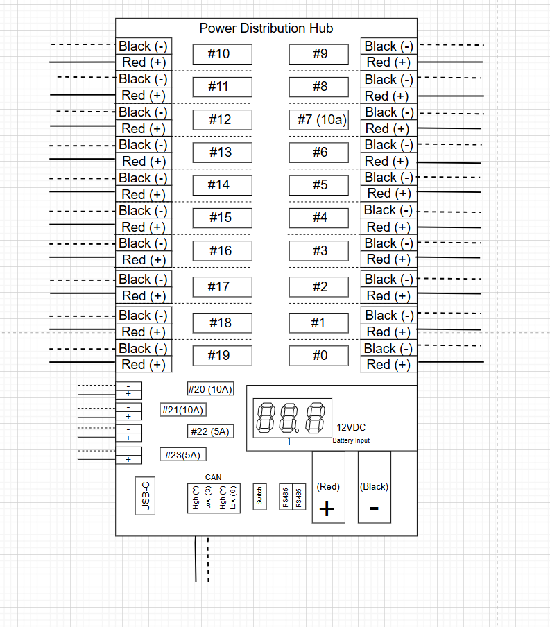
PDH and Breakers/Fuses
Power Distribution Hub (PDH), Breakers, and Fuses
Power Distribution Hub (PDH), Breakers, and Fuses
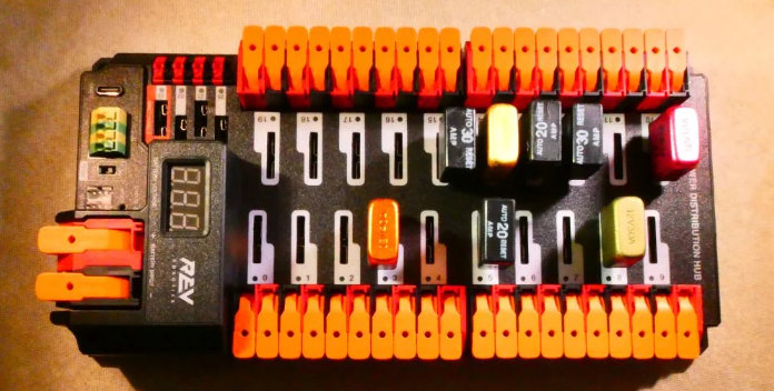
Usage
The power distribution hub, or PDH for short, distributes power to the entire robot. There 24 total ports, 20 for components needing a larger power supply and 4 who need smaller supplies. There are also 2 ports to support a CAN chain (yellow and green ports).
When plugging components into the PDH it is best practice to use breakers or fuses. If there is ever a power surge breakers and fuses will be able to stop it from reaching the more expensive and important parts. There are different types of breakers and fuses based off of the amount of amps they let through. The main difference between breakers and fuses is their reusability. Breakers are reusable due to a small sheet of metal which bends breaking a circuit when heated to a certain temperature. Fuses are not reusable as when to much electricity flows through it it heats up and pretty much melts itself.
How to Wire/ Connect
For the CAN chain and the 4 smaller ports they need a 22 gauge wire with a ferrule. In order to insert the wire into the ports use a small flat head screw driver and press down on the square button with a diagonal cut located directly above where you insert the wire. Hold it down until the metal part of the ferrule has been inserted then let go of the button to lock the wire in place.
In order to connect to the battery to get power use 6 gauge wire. On the bottom left on the image above the bigger red and black ports is where you insert the wires. First strip the wire bare by about a 3/4ths of an inch and then insert the bare wire into the 2 ports. Lift the orange lever above the 2 ports to unlock it, then insert the wire, push down on the lever to lock in the wires.
For the 20 larger ports 12 gauge wire is recommended. No crimps or ferrules are needed, instead just strip the wire until roughly 3/4 of a inch of it is bare metal. There is a large lever directly above the hole where the wire should be inserted, pull up on the lever to unlock the port and once the wire is fully inserted so no metal is visible push the lever back down to lock it into place.
Breakers are placed in the white slots behind one of the 20 port taking up majority of the PDH. Fuses are placed in the smaller slots above the CAN chain ports.
(NOTE! Breakers need to be inserted in a certain way. If you look at the bottom of the breaker where the 2 prongs are sticking out you will see that the prongs are off centered. When placing the breaker into the PDH make sure the side furthest from the 2 prongs is lined up on the right or on the same side where there is more white paint marking where to insert it)
Orange Pi and Arducam System
This section covers how to wire the Orange Pi and Arducam System. This is a vision system that we use as an alternative to the Limelight system.
Background
Orange Pi
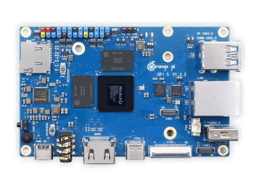
Figure 1
The Orange Pi (Figure 1) is a high-speed single board computer powered by a buck converter which is connected to the PDH. It requires 5 volts to power it this is where the buck converter comes in.
Buck Converter
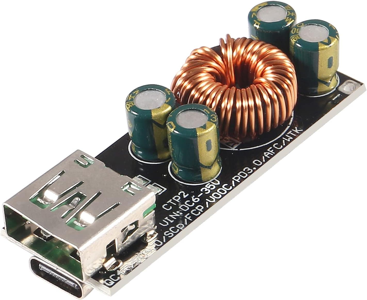
Figure 2
The buck converter is shown above in Figure 2. Our particular converter is a DC to DC converter which means it transfers the same type of current. What the buck converter does is it turns the 12 volts from the PDH to 5 volts.
Arducam
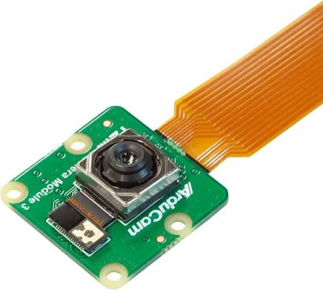
Figure 3
The arducam (Figure 3) is a robust high quality camera module specifically created for processors like the Orange Pi and Raspberry Pi. In our system we connect the arducam to the Orange Pi via USB.
How to Wire
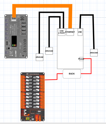
Figure 4
Wire Management
How to route wires
Good practices
“When in doubt, zip tie it out.”
(mukiewukie 2025)
Historically, a LOT of our matches have been lost due to easily preventable wiring issues that turned worse and worse.
So here I write in hopes of it changing in future seasons
Routing: The process of safely passing a wire, series of wires, or bundles of wires through an environment to reach the desired area of connection.
Our Methods of moving/protecting wires
-
Snakeskin
-
Allows wires to be protected in possible areas of vulnerability
-
Cable Carrier/Umbilical Cord
-
Allows for the linear movement of wires
-
Also protects wires
There are different methods of wire management that allow for a robot to successfully run
Methods of wire management also allow for tracing
Tracing: Seeing where a wire comes from and goes by following it.
Routing standards:
-
Battery wires zip-tied 4 inches away from the component.
-
Prevents wires from slowly being shook loose over time.
-
All wires are fact-checked (pull tested by another member)to prevent poor crimping and bad connections
-
Zipties are used to help the movement of wires towards components
-
Right angles are peak
-
Keep connections between wires visible and easy to fix in case of emergency
Mounts:
In the past FRC season, Reefscape, our controls team, had a hard time coordinating with our CADders about device mounts that we needed. Consequently, we are pushing for CAD controls CADders to help fill this gap and prevent any sort of miscommunication. We are planning on using Onshape to fulfill this task.
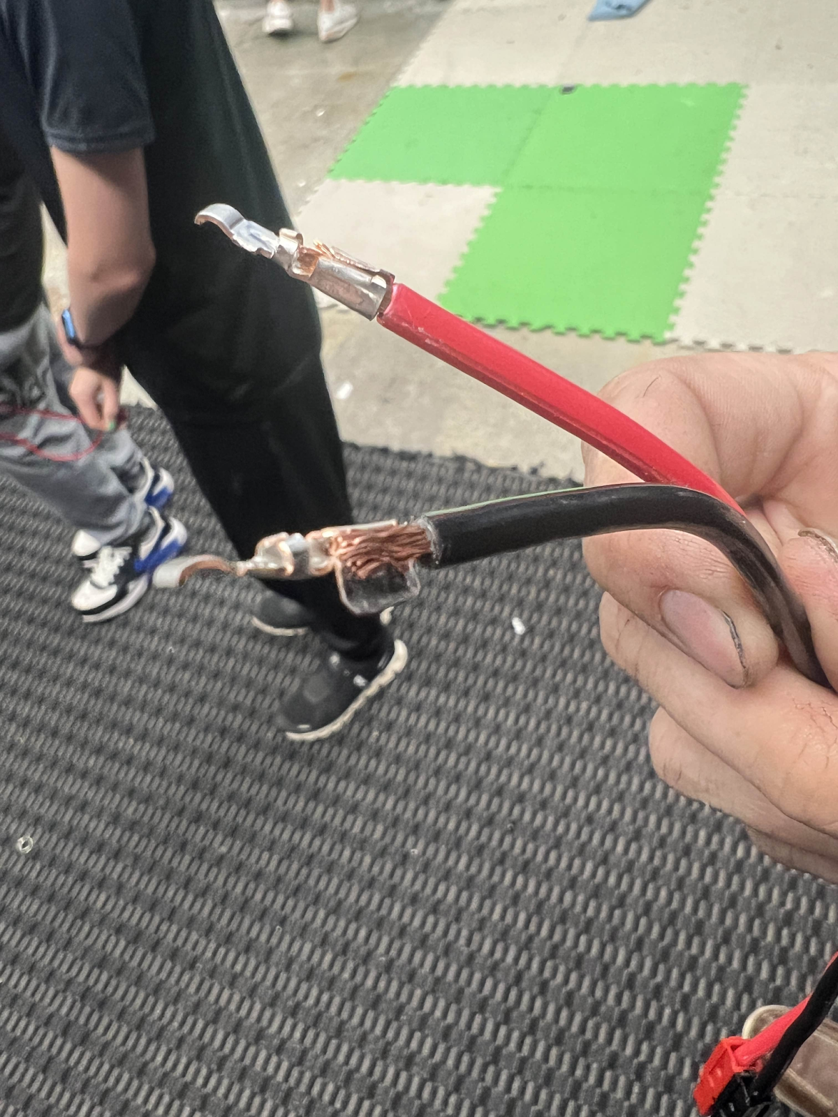
Crimping
Practices
Use a “Goldilocks Approach”
Too much exposed copper can lead to short-circuiting
Not enough creates a weak connection and can come out at the worst time
Have someone else pull-test your connections after you have crimped a wire (cross-check)
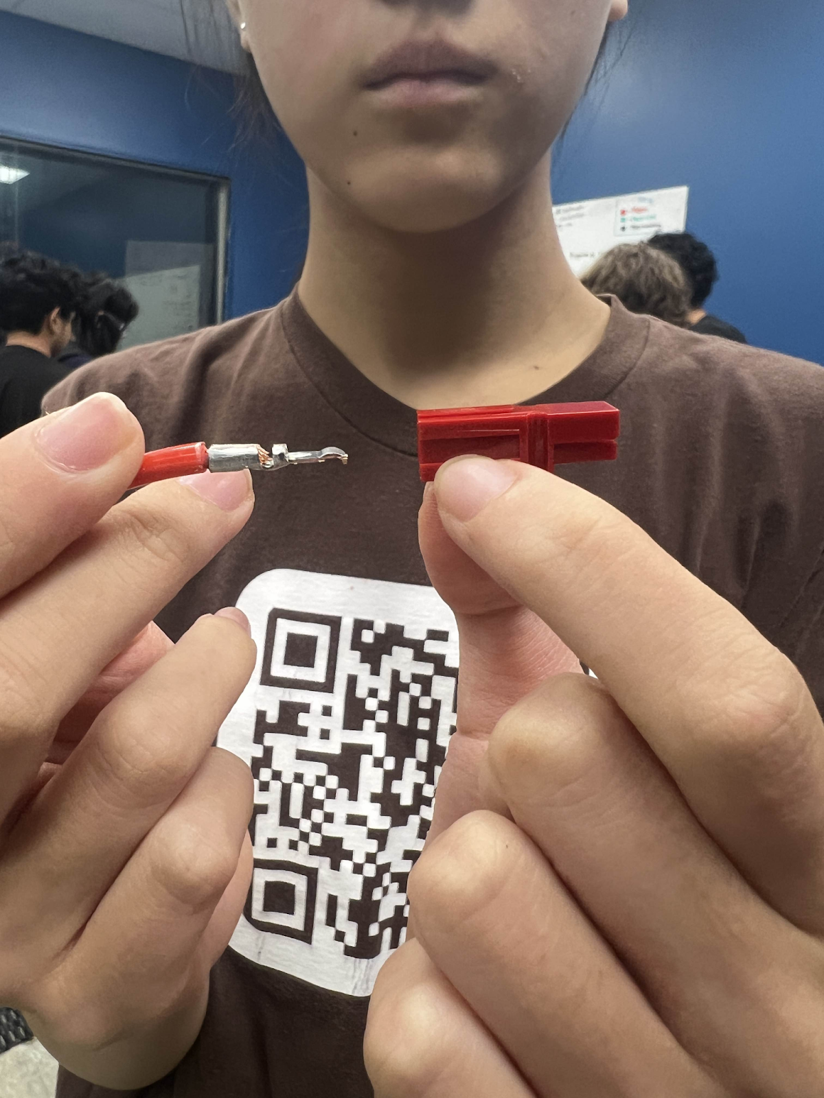
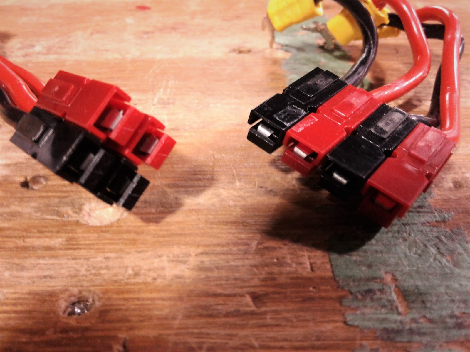
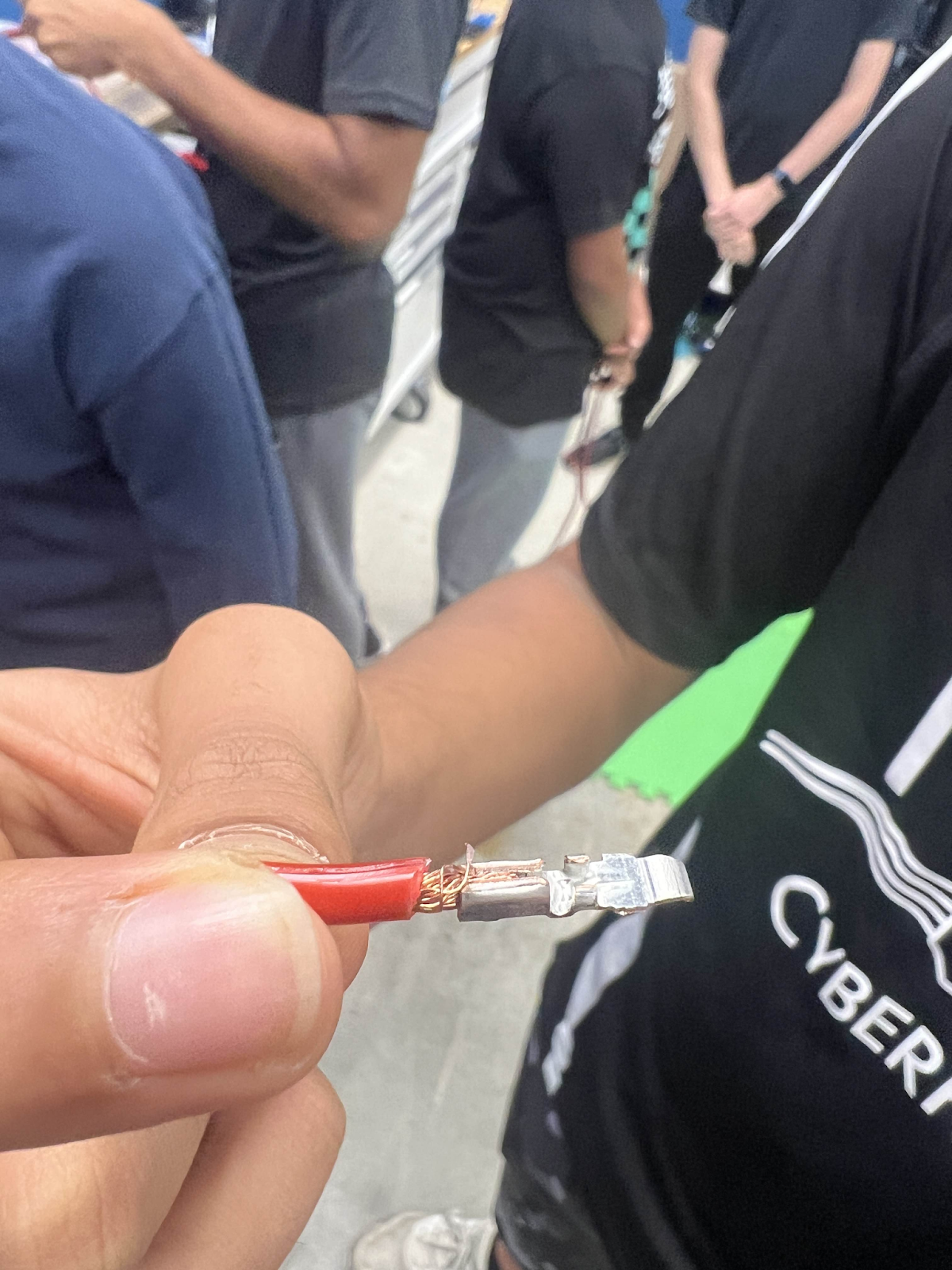
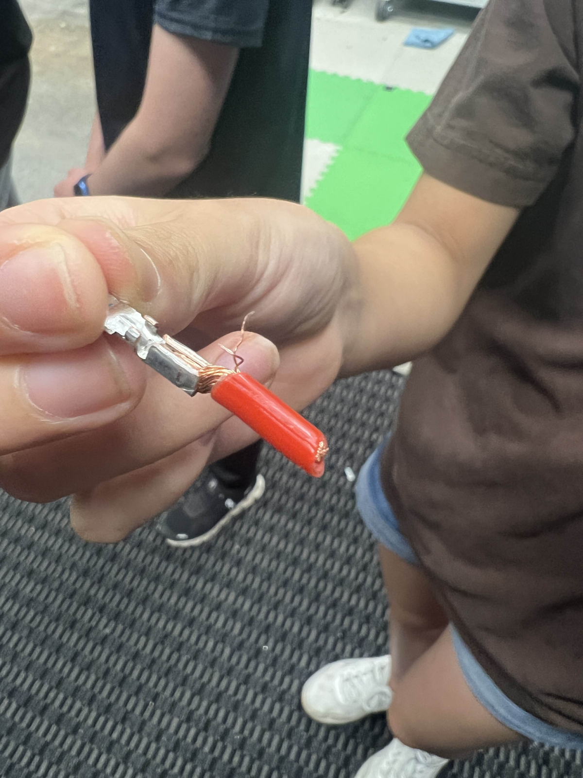
Anderson Crimp
Anderson/Powerpole Connectors
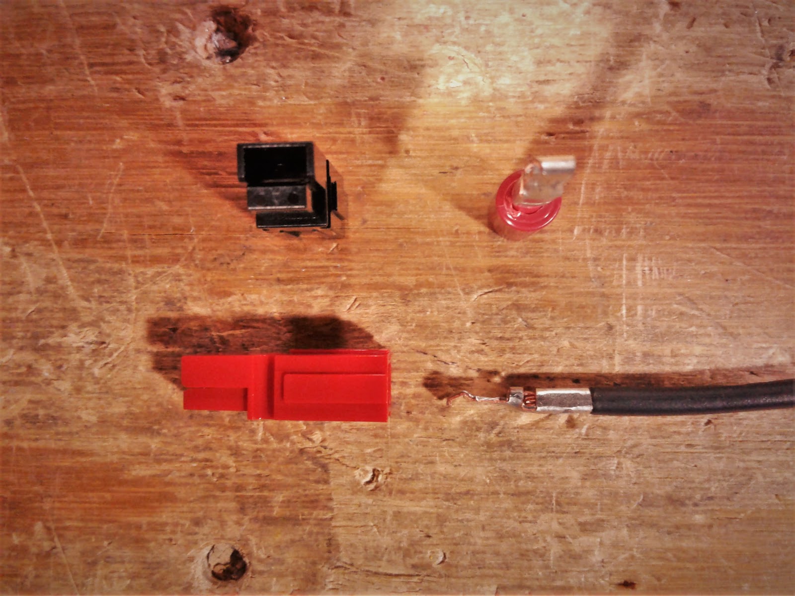
Great for anything that inputs/outputs power on the robot 10-20 AWG
(Powerpole Starter Kit - AndyMark, Inc)
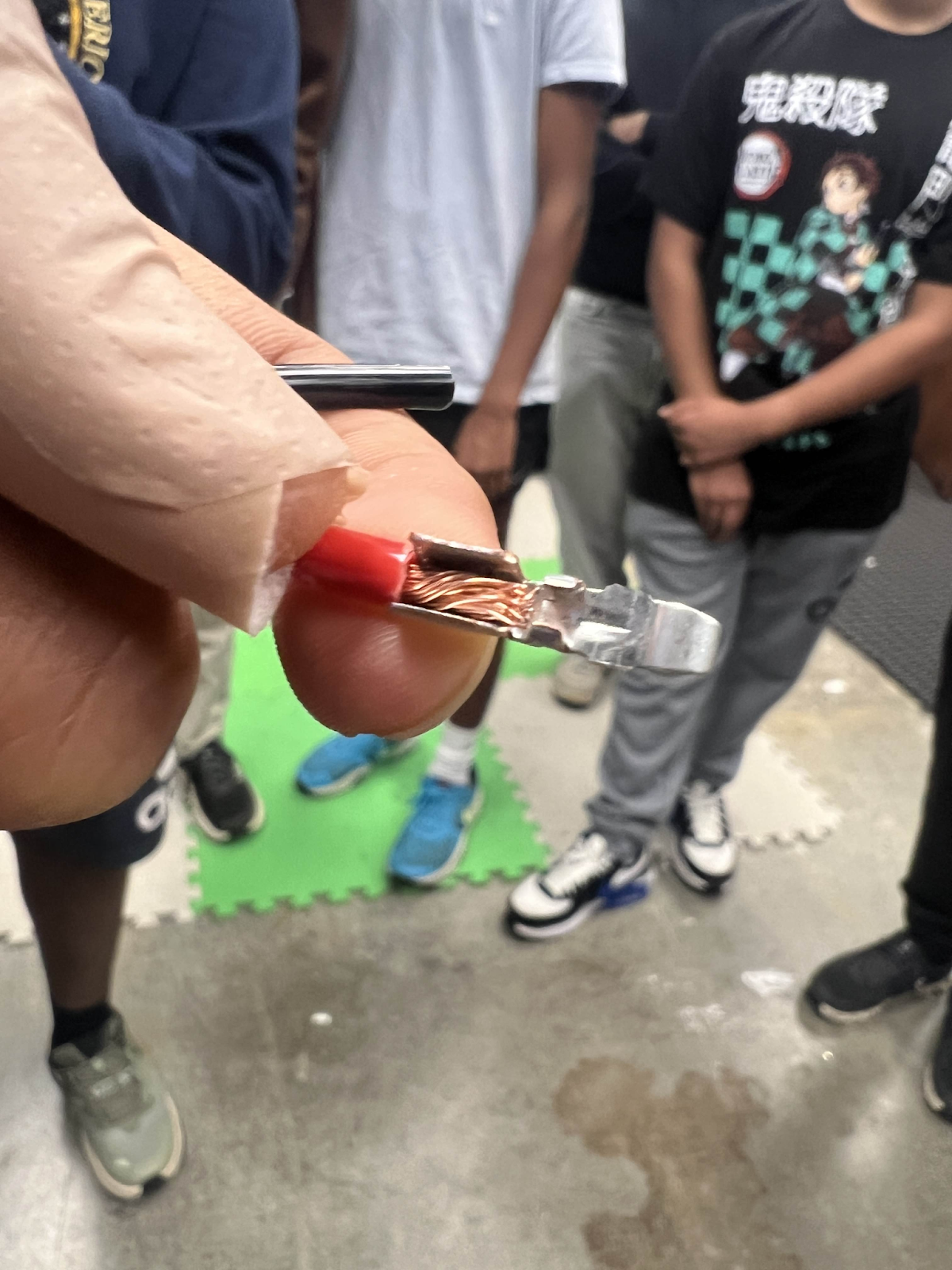
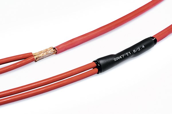
The first step in crimping and creating Anderson connections is to strip the wire of its insulation.

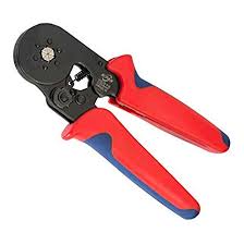
We typically use this wire stripper on the correct section for the specific Anderson gauge.
Once the wire is stripped, you want to prepare your Anderson crimp for the copper conductor.
It should be something like this:
From there, you want to take your Anderson wire crimper and put it into the middle setting (30).

Note: Our team has used mainly the middle setting for our wiring, though we have noticed less durability past 22 AWG
In assist to your crimping of Anderson crimps, some electrical students on our team have adopted the method of “prefiring” which includes putting the crimp inside the crimper and then inserting the wire. Any method of crimping is fine as long as the wire is completely inside the crimp, the crimp does not have any insulation inside, and the crimp is inside the crimper during the time of connection.
“Prefiring”:
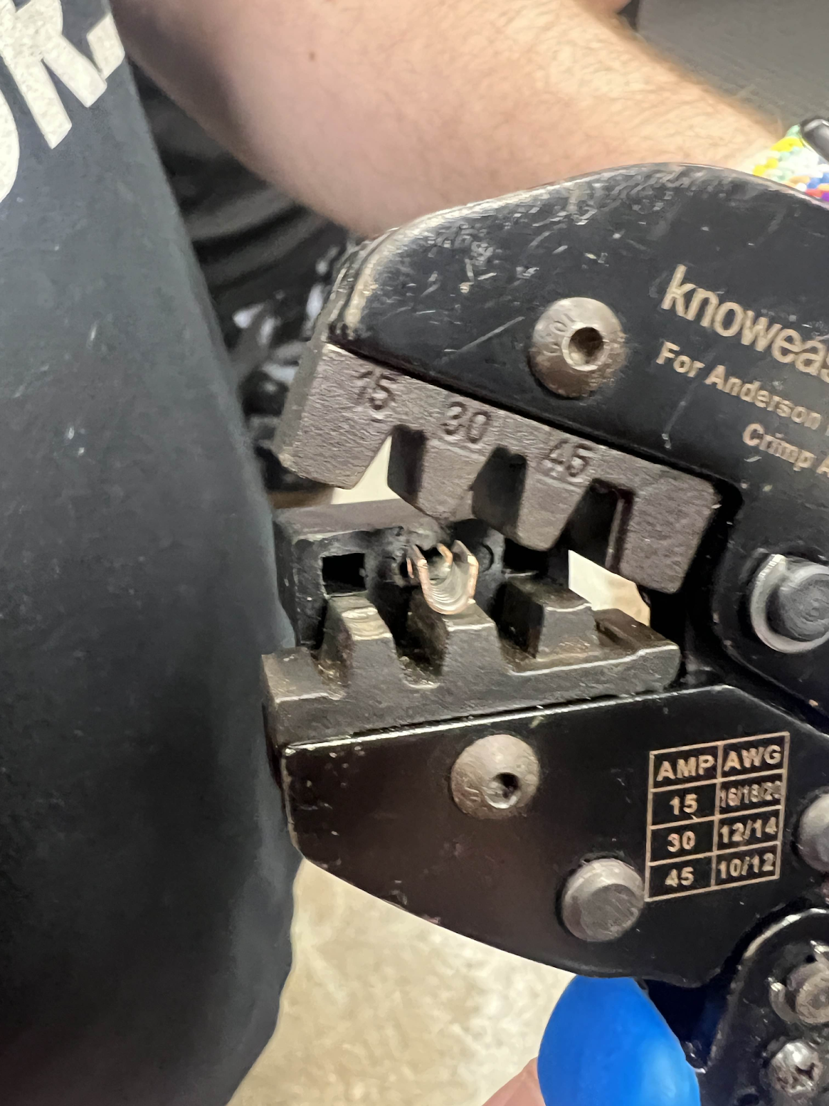
Note: Prefiring is a method that can execute poorly if misaligned, be sure to use what is comfortable but effective for you
Regardless of method chosen for Anderson crimping, your wire should look like this:
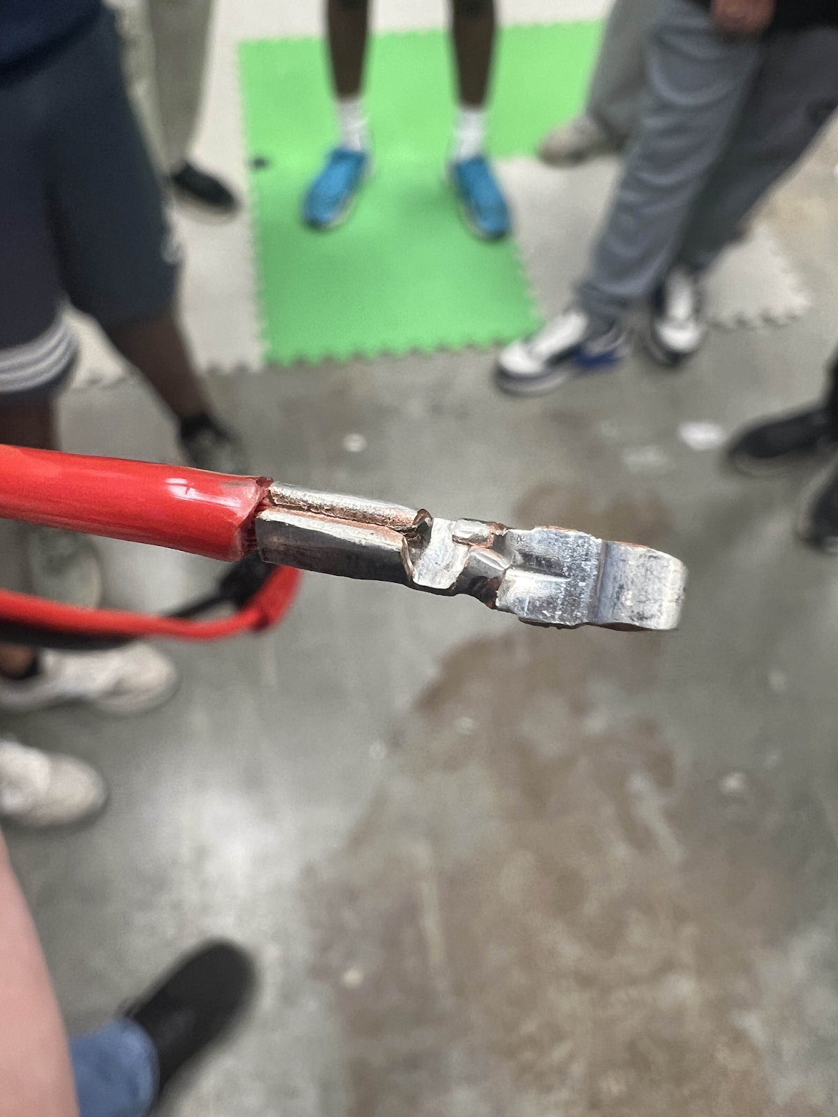
From there, you move onto putting the crimp into housing!
Make sure that your crimp is going inside the housing to look something like this and at this orientation.
From there, push into the housing and you should here a little *pop*
Afterwards, be sure to have someone pull test your connection.
Finished result:
What NOT to do:
Strand of wire out everywhere, crimp is not encapsulating all the wire strands
Crimp flag is way out leaving wire exposed and a bad connection.
AVOID LEAVING WIRE EXPOSED AND POOR CONNECTIONS TO THE CRIMP
Ferrule Crimps
Context:
We use these materials:
Ferrule Crimper

Wire Stripper
We use blue ferrules for 22-gauge wire
Ferrule crimps are probably the easiest crimps you can do on the robot. However, learning how to do them the right way is essential.
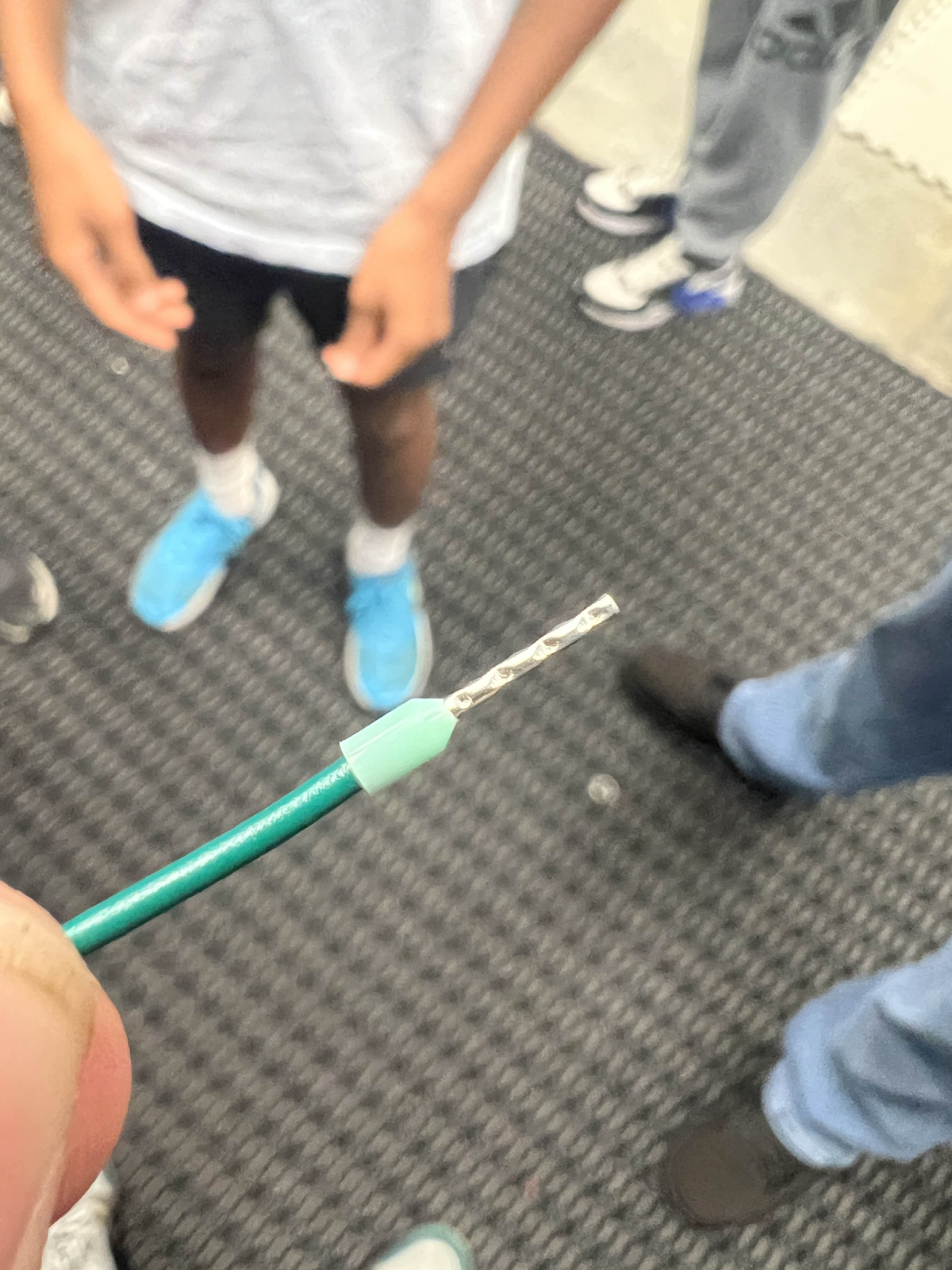
STEP 1:
Strip your wire -
You want to strip your wire so that it is around the length of the conductor on the ferrule being used (usually pretty long).
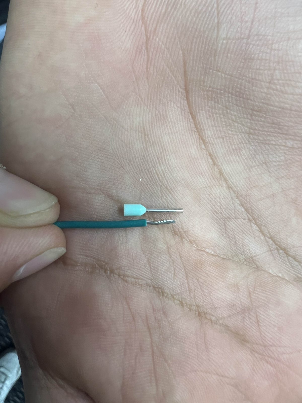
You should be looking at something like this
STEP 2:
From there you want to insert the wire into the ferrule crimp and try and make sure that the wire goes up high into the conductor (excess can be cut-off).
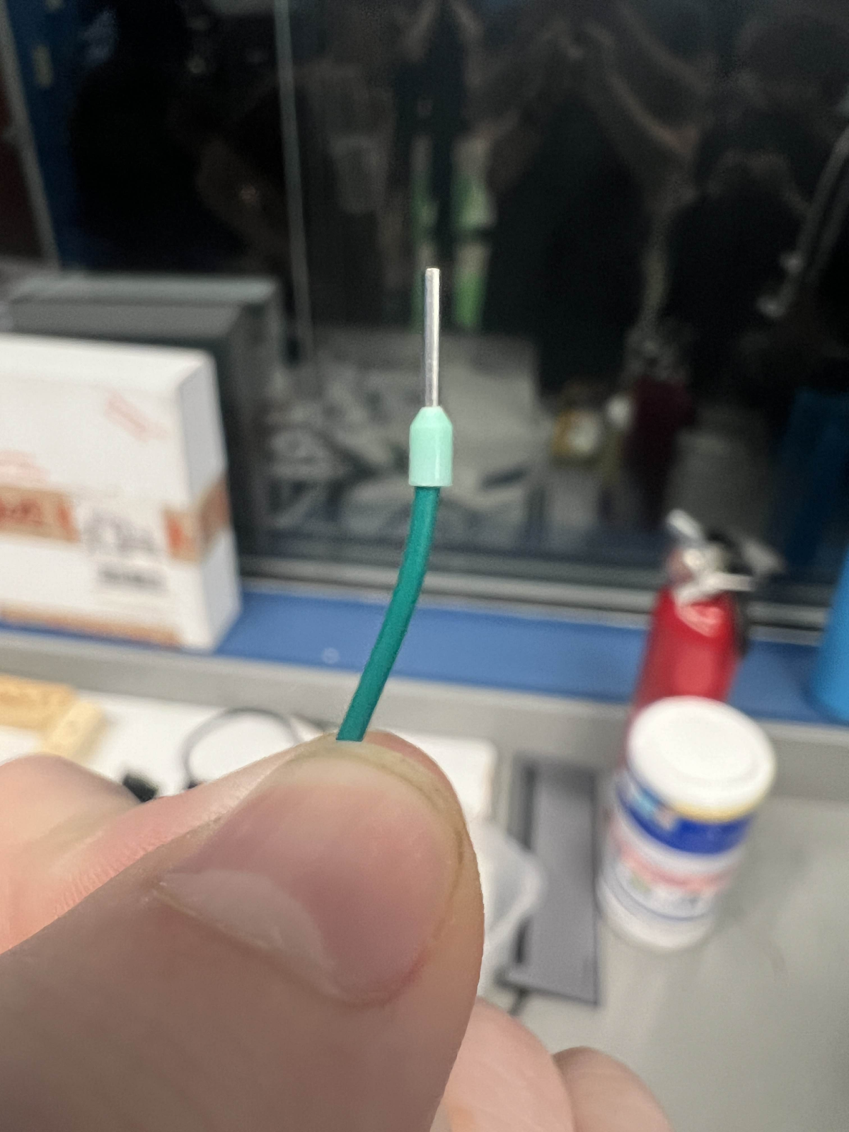
STEP 3:
After this you want to take your ferrule crimper to begin crimping!
When crimping ferrules, make sure that the conductor is the only thing inside the crimper and DO NOT crimp the insulation.
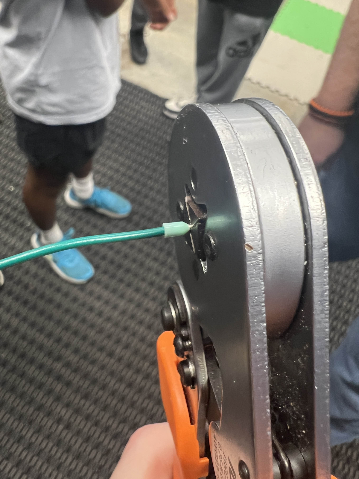
Finally, when done, your crimp should look like this:
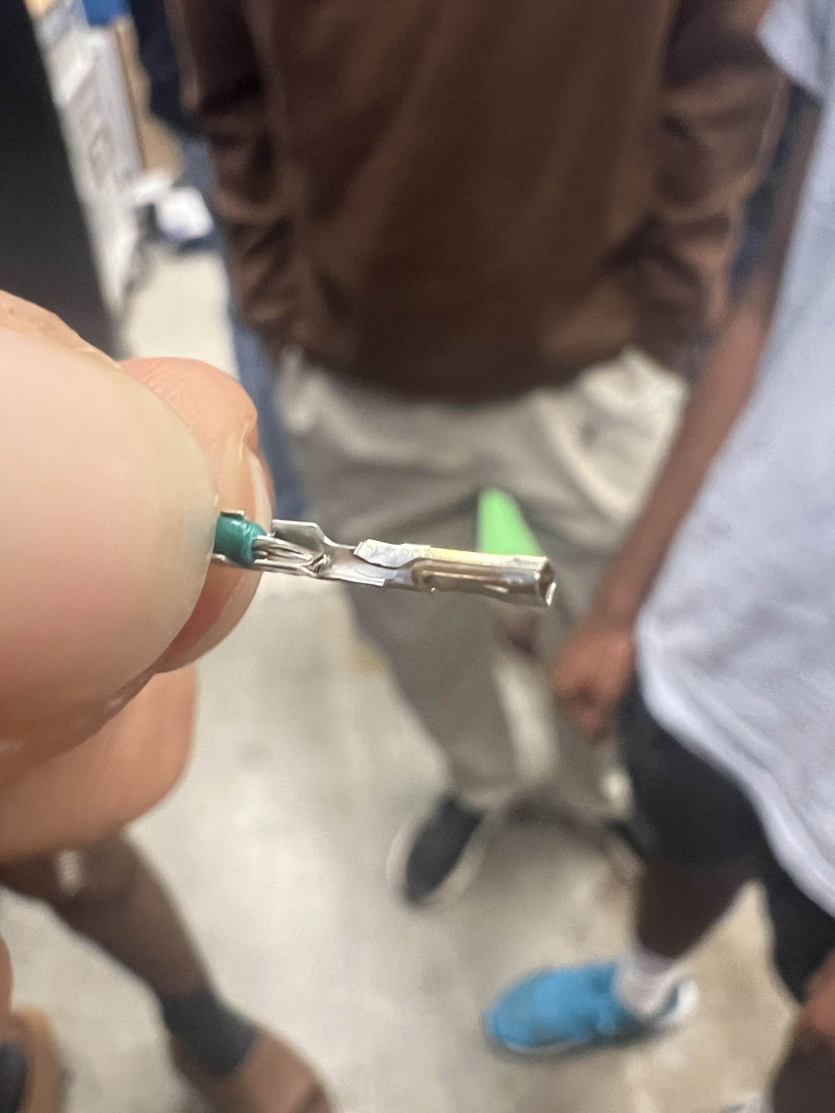
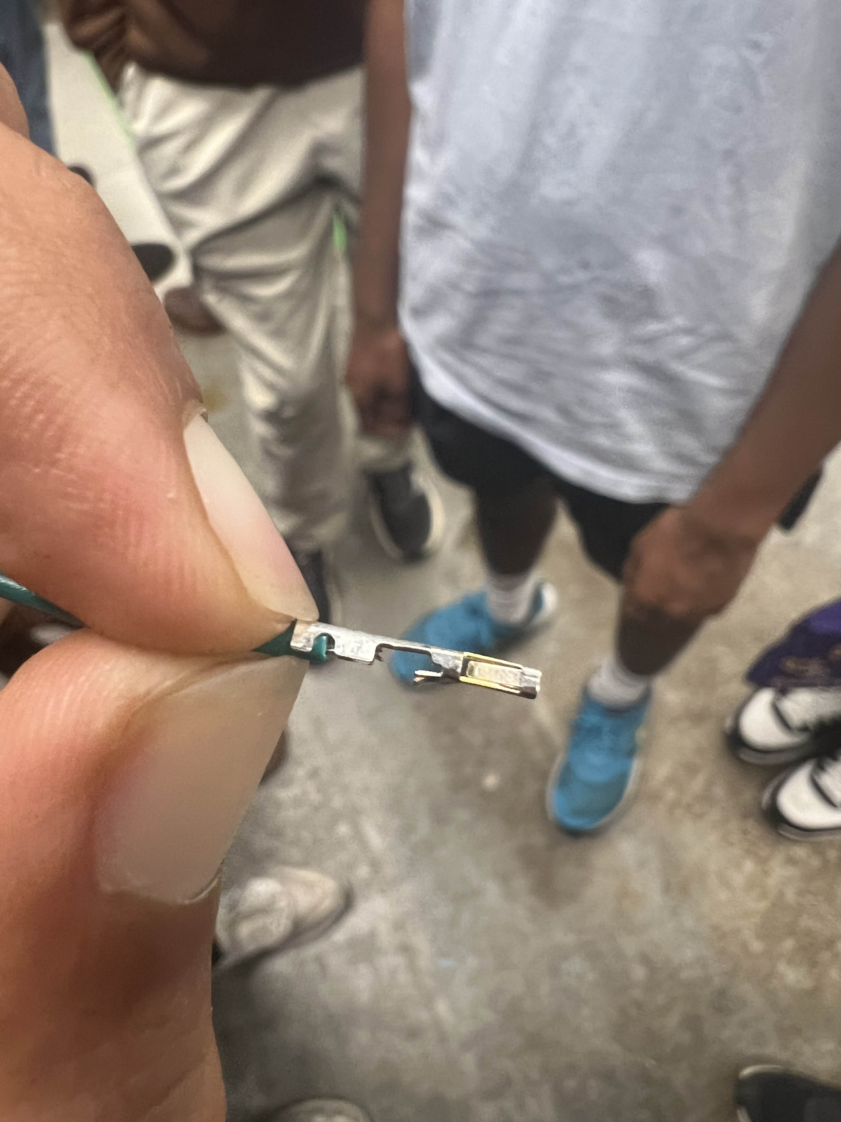
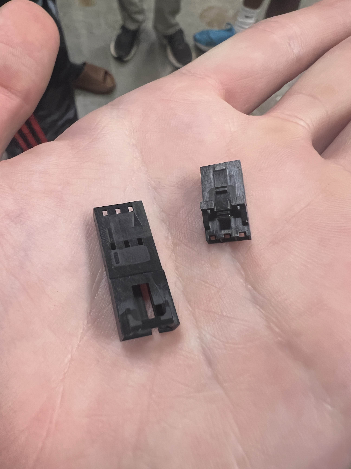
Molex Crimps
Introduction
Molex is the brand of crimps that we use in ensuring connection between 22 gauge wires.
This has been a challenge for some of our electrical students to mastering it is important for our robots power and CANbus.
Preparation
The first step in crimping these includes stripping the wire. You want to strip only a little off the wire because you will be crimping this inside the Molex. Less than half an inch is a good amount for this.
From there you want to take out a Molex Crimp
Before you start anything crimping-wise you want to make sure the crimp is cut properly. For male and female crimps the process is relatively the same.
Preparing Female Crimps:
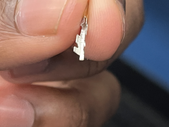
Figure 1
Your average female molex crimp will look like the image shown above in Figure 1. First you would want to utilize a blue pair of WORKPRO snips in order to get a clean, flush cut. Snip this flap off as shown in Figure 2 and Figure 3 below.
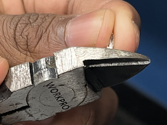
Figure 2
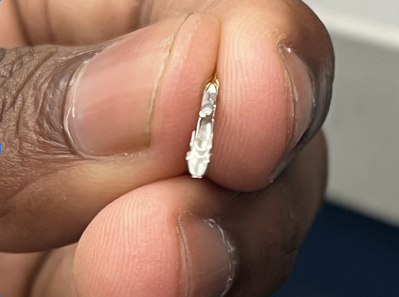
Figure 3
To note, females occasionally come with a flap on the top of the crimp. If the crimp comes with one, follow the same procedure as shown in Figure 2 and Figure 3 above.
Preparing Male Crimps:
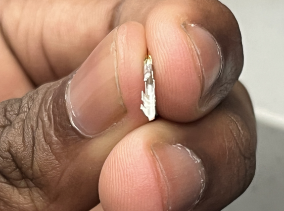
Figure 4
A normal uncut male molex crimp will look like the one shown in Figure 4. Grab a pair of WORKPRO snips and cut the flap off as shown below in Figure 5 and Figure 6.
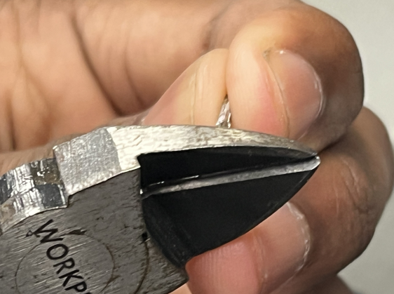
Figure 5

Figure 6
Next you would want to flip the crimp on the other side and clip this small little golden flap off as shown in Figure 7 and Figure 8. The finished product should have a similar appearance to Figure 9.
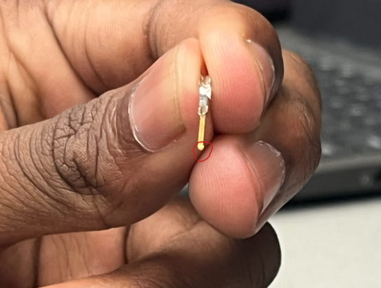
Figure 7
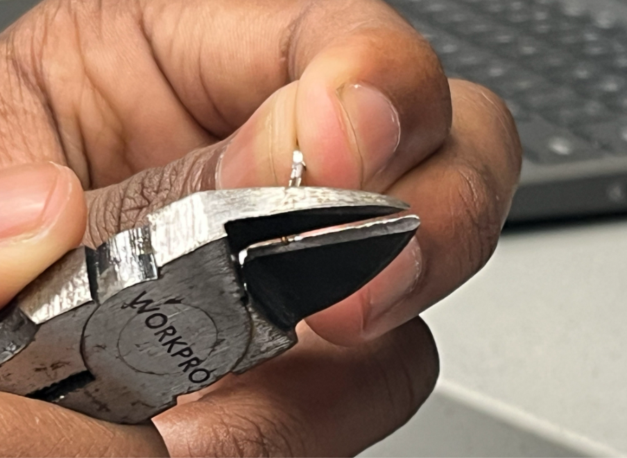
Figure 8
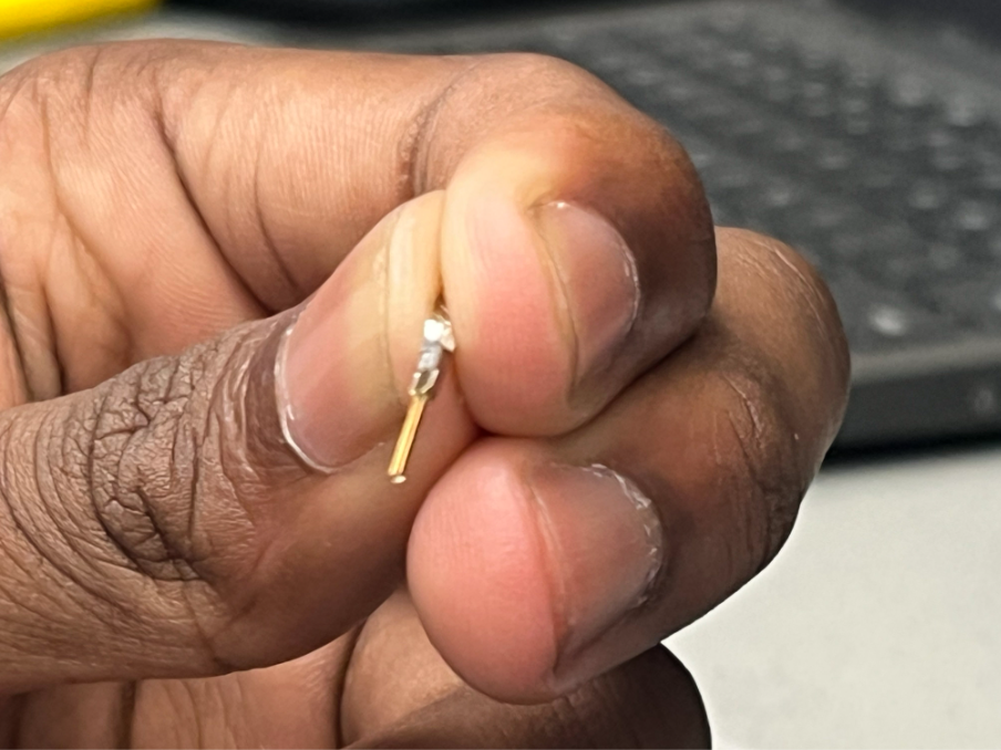
Figure 9
Great! You are now ready to crimp! First grab a pair of handy crimpers. There are two different type of crimpers we utilize. The first type of crimper is the Hozan P-707 this tool is comparatively more difficult to use than the Molex Premium Grade Insulated Hand Crimp Tool the second type of crimper. I will cover how to use both types of crimpers in detail below.
1. Hozan P-707 Crimping Instructions
From here, you want to adjust the molex crimp onto the stripped wire so that the “bottom” flap is on the insulation part of the wire and the “top” flap is on the copper wire. Make sure that you are not including too much insulation for the bottom flap and you want to be closer to the edge of the insulation.
This is a side view:
From there you are ready to begin crimping.
Take your crimp on the top flap to the side of the wire crimper that is labeled as “Conductor” and use the 1.7 Ridge in order to press down on the flap.
It should look similar to this:
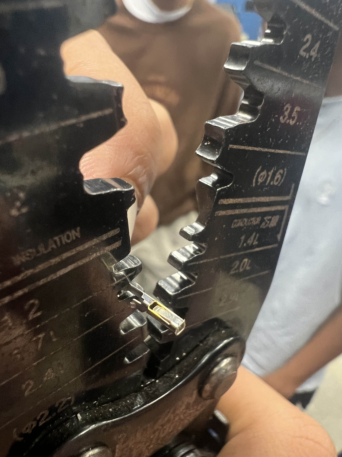
Take your crimp on the bottom flap to the side of the wire crimper that is labeled “Insulation”
You will use the 2.0 Ridge in order to press down this flap.
It should look similar to this:
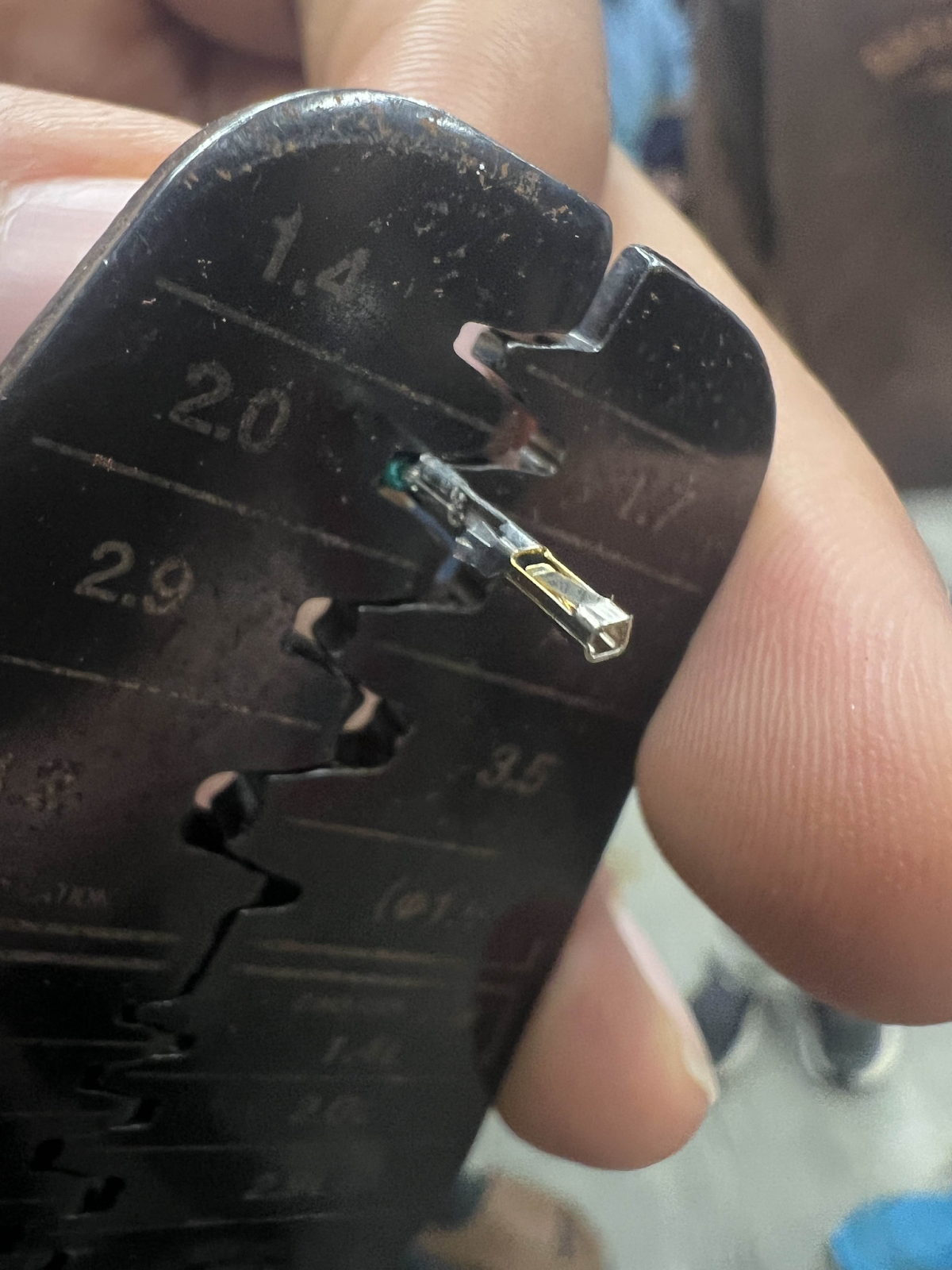
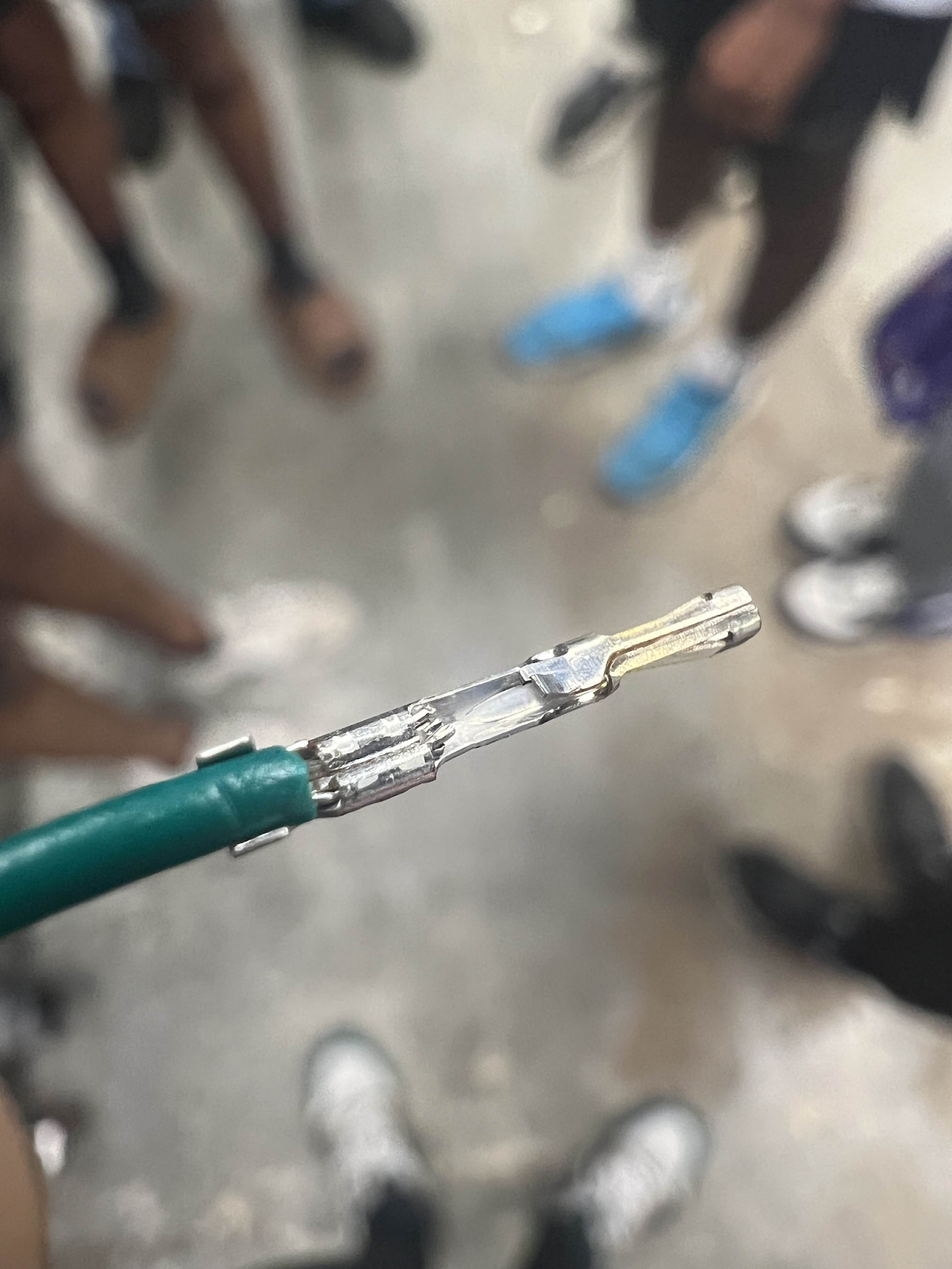
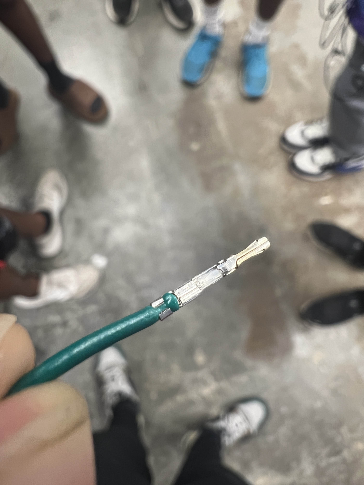
Your finished crimp should look like this:
Finally, to assemble your crimps into the housing.
The housing on the left is for Male Molex Crimps whilst the right is for Female Molex Crimps
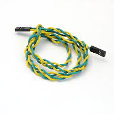
For standard FRC control system wiring, the black and red wires represent ground and power whilst the green and yellow wires represent CAN or Controller Area Network.
A rule that, as Mukesh quotes it is, “The lighter color goes onto the arrow while the darker color is on the opposite side” (FOR CAN).
To decipher this quote, it basically is a rule used to show where the different wires go in a housing.
For a 22-gauge power wire, the black (ground) wire is on the arrow while the red (power) wire is on the opposite side
For CAN, the yellow wire is on the arrow while the green is on the opposite side.
This is important as any changes in this can result in errors in either CAN or power.
Remember that red (power) is positive, meaning that it sends out power while black (ground) returns the path and completes the circuit. Mistakes in consistency can result in bad errors.
On your crimps, there is a little flap that sticks out of the crimp:
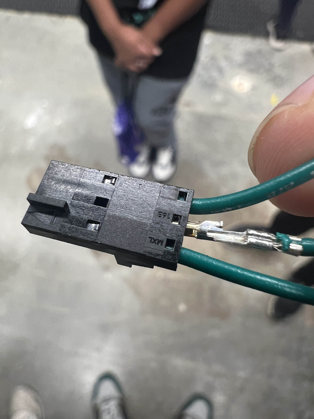
This is what connects to the housing.
Be sure that when you stick a crimp to the housing, the flap is going up the side with the hole to make sure the crimp is the right orientation and locks.
As always, be sure to pull test and have someone else pull test.
Use this for quick reference to an ideal crimp:

Ethernet Crimps
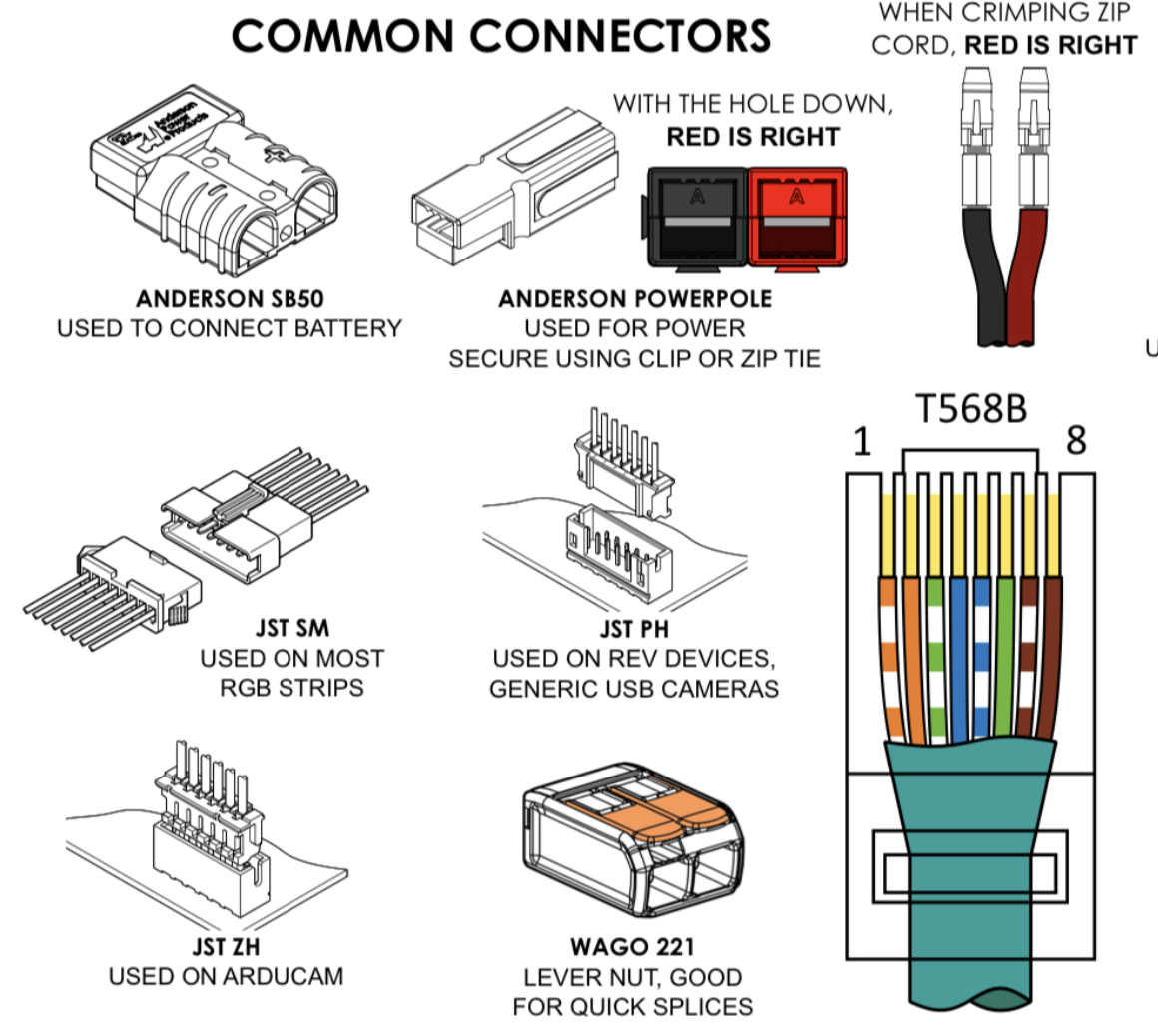
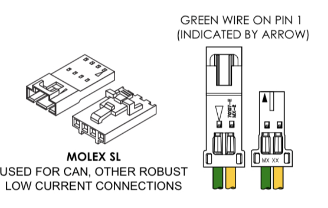
Common Connectors
Batteries
The powerhouse of the Robot
Preparation
Batteries are the powerhouse of the bot, essentially the mitochondria. Crimping and managing these batteries are essential to a successfully running robot that supplies power as it should.
I take heavy reference from the Zebracorns (Team 900’s) Battery Paper.
(Team 900's Battery Paper Chief Delphi Post)
1. How you begin
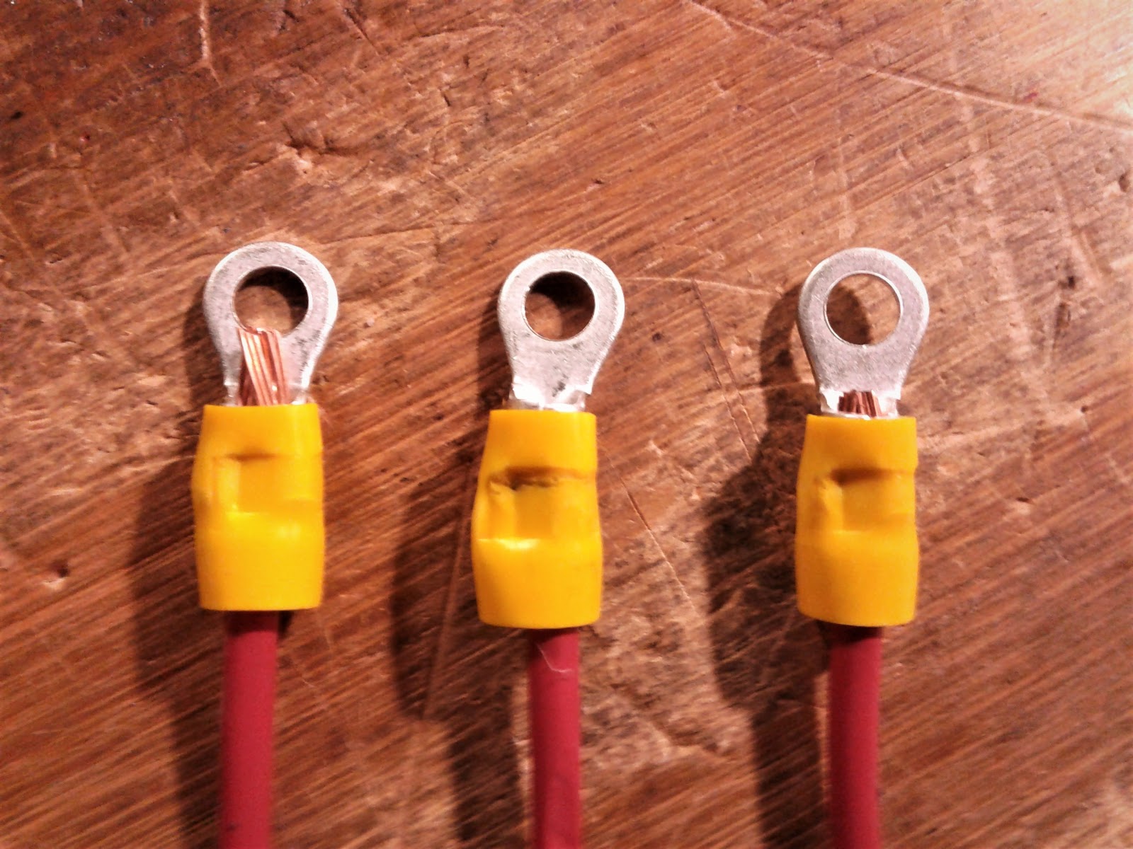
- Cutting out the battery wire is essential, and we plan on using 12 inches of battery wire for two-gauge wire to ensure strong connectivity.
- From there, the wire must then be stripped and crimped unto the lug crimp to ensure connection.
- You will also need to crimp the other end of the battery wire for it to be put into the SB Connectors.
2. Connection to the terminal…
- Use of any washers can reduce energy transfer and we usually cover our terminal connection with electrical tape and heat shrink.
- You know your battery isn’t working optimally if it shows visible signs of poor connection to the terminal.
Good way to check your batteries at comp:
Good Practices
Good practices:
-
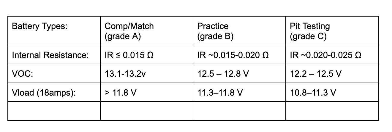
Using a battery beak can help determine the battery connection and “charge.” A common misconception is that if you see "Good 130%" on the battery beak, it's a good battery to use, but that's actually wrong. The 130% only says how long it has been off the charger, not the actual charge of the battery. You should actually be looking for the resistance and the voltage at 0 amps. The resistance should ideally be under 0.015 ohms(15 milliohms) for comp, and 0.020 ohms (20 milliohms) for practice or testing, and the voltage should ideally be over 13 volts.
-
However, you might need several batteries during the competition to ensure you have good batteries for all matches.
-
Labeling batteries is essential in the pits to organize and make sure you aren’t using a “dead” or used battery. It is also useful to make sure the battery is where it should be.
Scenarios
Scenario Responses:
-
If a battery is suspected not to work as it should, you can disassemble (like we did at World Champs 2024-2025 season) and check the connections, and make sure everything is as it should. This can include looking at the terminals and the connection between the power wires and making sure it is firm. Reassess and act appropriately.
-
If a battery is leaking quickly, neutralize the acid leaking from it and use battery spill kits. Try and keep the area safe and alert volunteers or officials if needed
Testing Batteries.
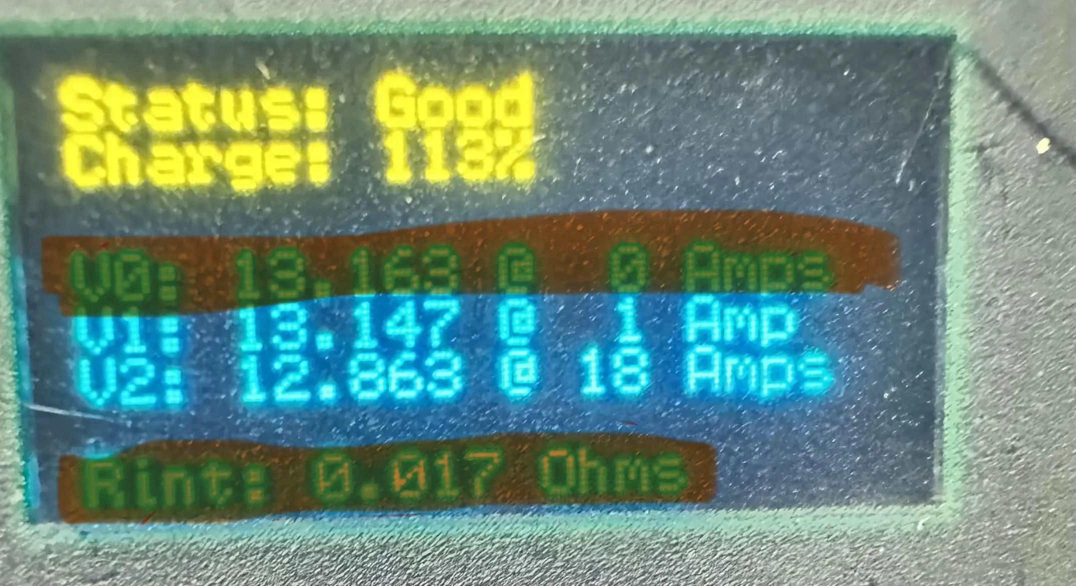
Battery Beak
The battery beak is a device that allows you to quickly test a battery and see if it is good to take and use. The main points to look for on the battery beak are V0 and the internal resistance. The voltage should be over 13 volts and the internal resistance should be under 0.015 ohms(15 milliohms).
Automotive Tester
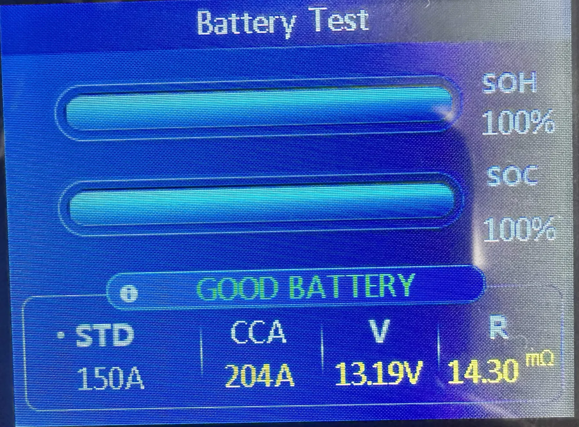
The automotive tester gives more accurate testing results and more data than the beak. It gives you the voltage and ohms just like the beak, but it also gives the SoH(State of Health), the SoC(State of Charge), and the CCA(Cold Cranking Amps). The SoH and SoC should ideally be 100%, but the SoH will go down over time with use. The CCA should be over 150.
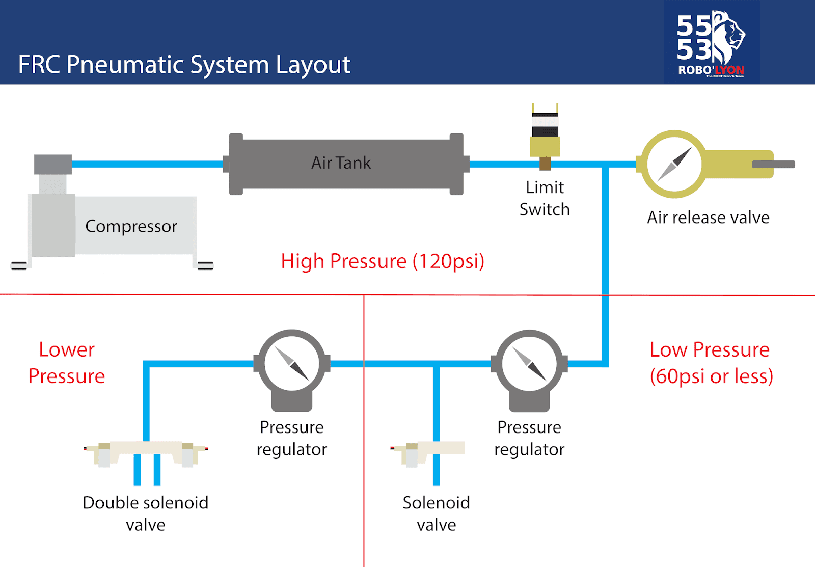
Pneumatics
Compressed Air
What you need to know
Probably my personal least favorite part of electrical: Pneumatics
Pneumatics: The use of compressed air for quicker and faster movements that a motor can not provide
Parts:
Compressor
Charges air for components on the robot.
Pressure Switch
Works with a controller to tell the compressor when to shut off.
Solenoid Valves
Electronically controlled valves.
Pneumatic Controllers
PH/PCM
Controls the compressor and up to 8 solenoids.
It gains input for a pressure sensor to control the compressor when needed.
CAN based communication
Pressure Switch
Manages amount of pressure in the robot
Acts as “go-between” for the PCM and compressor.
Dump Valve
Releases (or dumps) all air out of the robot.
Electrical Solenoid Valve(s)
Actuates the different sides of a pneumatic component such as a shifter or piston. Can be single or double action.
Compressor
Charges air for components such as pistons and shifters on the robot. FRC-legal amount of air is 120 psi (pounds per square inch).
Emergency Relief Valve
Keeps the air under 125 psi if the compressor or pressure switch is working incorrectly
Pneumatic Practices:
-
For cutting tube use a special tube cutter to get clean cuts
-
To make seals tight we use 2 and a half layers of teflon tape for brass fitting threads
-
Make sure tube don’t kink or fold and don’t touch the tips of tubes
General Pneumatic Layout:
NOTE: We usually don’t use pneumatics unless the robot requires quick movements (in one motion) in a short time span
Pneumatics 101 Presentation
Electrical Documentation
Everything you need to know about Electrical Documentation for the upcoming FRC season!
Documentation Standard
As a representative assembly, the Electrical Subteam has decided to use draw.io as the Electrical Standard for the FRC 2026 season, Rebulit.
We will be using this website for our documentation on Electrical Schematics and Layouts.
Quick Distinction:
Electrical Schematics (in our terms)
- Component diagrams that depict the connections of ports and the port numbers that they connect to
- Depicting motors and what PDH port they connect to
- Showing the flow of the CANchain through the various components
- Depicting the individual ports of the PDH and their connections
-

Electrical Layouts
- Diagram of the robot and the various components connected. This also entails the display of wiring between these components on the robot
-

- Does not include wiring, but you get the point ^
-
Electrical Template for Documentation
https://drive.google.com/file/d/1hX2cgcBHF-MwaM-B19c196EsSkeuA8Ys/view?usp=sharing
NOTES
When using this template:
- Be sure that you are following FRC Electrical Standards
- Be prepared to have your Electrical Schematics reviewed by the team
- Make sure it is thorough and realistic
- Understand that each section has inputs based on the specificities of robot
Resources for Draw.io
Video tutorials on draw.io
https://drawio-app.com/tutorials/video-tutorials/
https://www.youtube.com/channel/UCiTtRN9b8P4CoSfpkfgEJHA
https://www.youtube.com/watch?v=bN6i6dsoZTs
https://www.youtube.com/watch?v=WlCKv49Pkvg
Example Documentation from Other Teams
https://github.com/sikaxn/FRC-Custom-CAN-Sensor/wiki/6.-Wiring-and-powering
https://www.team5026.com/Sprintbot_(2025)#CAN_Chain_&_Devices
Creating Electrical Documentation
Starting your Documentation: Overall Drivetrain Layout
Hey there! If you're reading this you're trying to create electrical documentation of your robot! In order to facilitate your journey of creating your electrical documentation, this tutorial is split up into simple sections. The program we utilize as of 2026 is draw.io.
1.0 - Creating a Basic Shape of a Drivetrain
1.1 - Outlining major points of interference (POI's)
1.2 - Identifying Different Types of Drivetrains and How to Depict Different Types
1.3 - Conclusion
1.0 - Creating a Basic Shape of a Drivetrain
To begin, you must have a picture of your drivetrain in CAD in order to get a good idea of the shape of your drivetrain. Utilize the shape tools in draw.io to copy the shape of the drivetrain as shown in Figure 1 and Figure 2. For this drivetrain it is a simple square shape but other robots can have different shapes such as 435's 2026 robot which was in shape of a triangle.
Figure 1

Figure 2
1.1 - Outlining major points of interference (POI's)
In robotics, a Point of Interference (POI) is defined as any area where wiring cannot be routed or is at risk of damage, such as the space beneath an elevator shaft where moving parts could easily crush or sever the cables. When it comes to making schematics POI's are extreme danger zones do not cross zones if you will. No wires or electrical components should be in a POI. As a general rule of thumb any area that may grind, chew, sever, or damage a wire in any way should be avoided.
Let's look at some examples on where to not route wires.
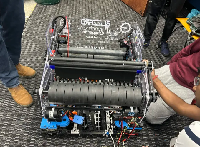
Figure 3
The image shown in Figure 3 is a shooter of one of our robots, Blizzard. Now let's say we take those wires and route them to other components through the flywheels (the large black wheels). This is why knowledge of how mechanical components is beneficial even in electrical. Flywheels would completely destroy wires as they are meant to spin at high revolutions per minute
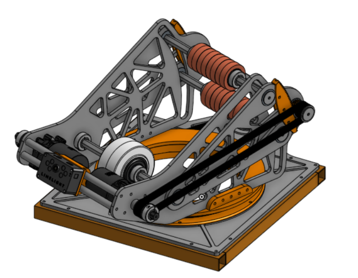
Figure 4
Another example is shown in Figure 4 this is an image of a turret from this year's game. The POI I want to focus on is at the base of the structure. This might not be a very obvious POI at first but when you look closer at it and understand how it functions this turret is designed to rotate. If you wanted to power the mounted limelight on the front you would want to avoid placing wires in the circular orange section. The reason you wouldn't want to do this is because wires can easily get pinched and damaged in between these parts.
If you still have trouble identifying POI's when designing wire routes talk with a veteran in your subteam about where to route and not route wires.
1.2 - Identifying Different Types of Drivetrains and How to Depict Different Types
Note: This is not a full detailed lesson on drivetrains/drivebase designs. This is just a lesson on how to depict drivetrains in your electrical documentation. For more information visit the Drivebase Design page.
In FRC there are many different types of drivetrains but I'll only be highlighting three main types and how to depict them in your documentation. These three main types are Tank Drive, Swerve Drive, and Mecanum Drive. Our robots from 2024, 2025, and 2026 all use Swerve Drive. Below in Figure 5 a drivetrain with tank drive is shown.

Figure 5
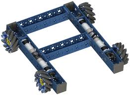
A tank drive consists of 4 or more wheels split evenly between two rows. It's major POI's of this system is outlined above in Figure 5. You don't want to put wires in the wheel areas as they will get damaged in these areas. A 3D image of a tank drive is shown in Figure 6 to better your understanding of how it looks bare.
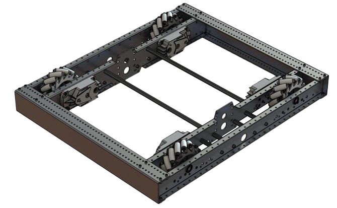
Figure 6
Note: There should always be motors powering these wheels contact your CAD team and discern if they will interfere with your wires or components at all.
Next is Swerve Drive. It contains four different swerve modules for square shaped robots the number of swerve modules can change change for drivetrains with a different shape. In Figure 7 a schematic of a drivetrain with swerve is shown. Then in Figure 8 a bare 3D model is shown.

Figure 7
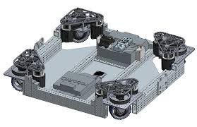
Figure 8
Next is Mecanum Drive. Mecanum Drive is similar to tank drive in that it is four wheels except they are smaller and have little wheels around them. You can depict them in your documentation exactly as shown in Figure 5 and scale them to their appropriate size. A 3D model of Mecanum Drive is shown below in Figure 9.
1.3 - Conclusion
In this section, you've learned how to create a drivetrain schematic. The next step is placing basic electrical components.
Detailing your Documentation: Adding Main Components
Here we go, detailing your documentation!
2.0 - PDH Placement
2.1 - Systemcore Placement
2.2 - Motor Placement
2.3 - Sensor Types and Placement
2.4 - Conclusion
2.0 - PDH Placement
A PDH (Power Distribution Hub) is used to distribute power from a battery through the robot to components that require power. Although it is recommended to talk with the Electrical subteam on where to place the PDH, you should place the PDH in an area with few mechanical points of interference, where wires can be easily traced and managed, and where important wires are clearly distinguishable from the rest. A clear example is shown below in Figure 1.
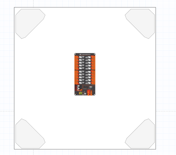
Figure 1
2.1 - Systemcore Placement
The Systemcore is the brain of the robot that gives out singles to different components through the CAN chain. You should talk with the Electrical subteam lead about the Systemcore placement, but you should position the Systemcore so it's readily accessible to both the radio and the RSL. To keep wiring clean and easy to trace, consider placing it away from the PDH, since that area tends to have a high concentration of wires. A clear example is shown below in Figure 2.
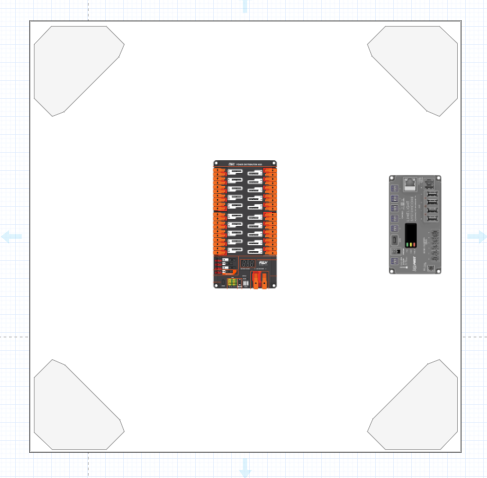
Figure 2
2.2 - Motor Placement
A motor is a device that converts electrical energy into mechanical energy. It is recommended to talk to the Mechanical subteam to place each motor, but you can orient each motor so its wires face the interior of the robot, keeping them accessible for troubleshooting. You should ensure all wire extensions are long enough to comfortably reach and connect to their corresponding electrical components. In you drive base you'll most likely be using swerve modules. These contain two motors each make sure to include these. A clear example is shown below in Figure 3.
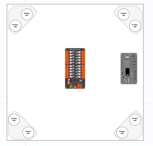
Figure 3
2.3 - Sensor Types and Placement
There are many types of sensors, including CANRange, CANCoder, Limelight, Pigeon, and CANColor.
-
CANRange
-
A CANRange sensor is a type of sensor that has a laser detection system. So anything that passes through the CANRange detects it and sends feedback through code. You should communicate with the Mechanical and Programming subteam for the placement, but you should place it where all its wires are out of danger from any mechanical component and where the laser points to the area you need it to point to.
-
CANCoder
-
A CANCoder sensor is a sensor used to measure the rotation, speed and the position of the component it is attached to. You should talk to the mechanical subteam for this components placement as they know where all the motors are going. It is recommended to orientate the wires so that they are out of the way of any mechanical component or danger.
-
Limelight
-
A limelight is a smart camera that detects April Tags throughout the field using code. It is recommended to talk to the programming subteam because they need to position the Limelight aiming towards the field.
-
Pigeon
-
This is a type of sensor that determines the gyro of the robot, so in simpler words, it determines if the robot is on a slant or flat ground. You mainly have to be mechanical because they need to be able to put it where there are no points of interference with mechanical components.
-
CANColor
-
This component detects color through code. They are used to detect gamepieces. You will mainly have to communicate with the programming subteam to place this component as it needs to face towards.
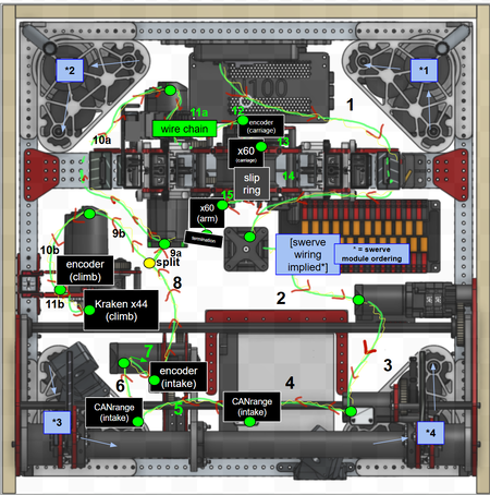
In the example (Figure 4) below four CANcoders are shown above the swerve modules.
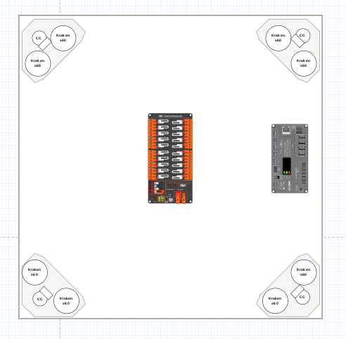
Figure 4
2.4 - Conclusion
This concludes this section of adding main components next will be adding wires and creating the document key.
Tips for Pit Crew and Competition
Preface
Competition can be stressful, especially when you have to look and make sure every device and wire on your robot is as it should be.
So here are some tips for the electrical pit!
Tips
-
Be sure that you know your robot!
-
If you were chosen for the pit crew, you probably know a bit about your robot.
-
This means that if asked by a judge, alliance member, or even just a visitor, you should be able to answer any question about your robot.
-
If a problem electrically occurs, you should be able to identify and attempt to fix it before your robot goes back to play
-
Always keep Spares!
-
You never know when the end effector of your robot might fall off, and keeping a spare of each major subsystem on your robot can save a LOT of time
-
For electrical, this can include wiring the subsystem exactly as it is on the robot to avoid confusion
-
You can also have extensions for wires, CAN and power, in case of any sort of emergency as it is easy to prep and store
-
Spares for devices are really useful if any device on the robot fails
-
Trouble-Shooting
-
Eventually, when something electrical goes wrong, you need to know how to act and when you can act
-
Usually, if the issue arises as a result of the robot breaking, that is much more prioritized than Electrical, as you can’t wire something that isn’t fixed
-
Be sure to prep in the meantime!
-
If a device isn’t giving off the right status lights, be sure to trace the wire that connects to it.
-
Try and have a basic memorization of your wire movement and what connects to what
-
I would recommend labeling wires with heatshrink to maximize time
-
Make sure that all devices are seen on Phoenix Tuner and functional (systems check)
Basic Terminology
Terminology
Basic Electrical Terminology
Volts (Power), V
The potential difference in charge between two points
The size of the force that sends the electrons through a circuit
Amperes (Current), Amp, I
The unit used to measure electric current
The number of electrons flowing through a circuit.
Watts, W
A measure of the rate of energy transfer of an appliance
The rate of energy generated or consumed
Ohms (Resistance), 𝝮
A measure of the opposition to current flow in an electrical circuit
Circuit:
A closed loop of conductive material.
Continuous flow of electric current. Positive to negative or ground. (+, -)
Series:
Components are chained together from positive to negative to positive, etc.
Parallel:
Negative to Negative and Positive to Positive
CANchain -
The chain of CAN devices and their connections gives information to each other. Also referred to as CAN bus, there may be multiple for different parts of a robot.
Electrically, the FRC CAN network is a two-wire bus, designed to allow dozens of devices to talk to each other with a single network.
Needs two 120-ohm resistors to terminate the ends of the bus.
Bandwidth:
the ability to measure a signal
Multimeter:
-
Electronic measurement tool
-
Used to measure various electrical values
-
Analog vs Digital
Must-Knows
FRC Electrical Must-Knows:
|
COMMON TERMS |
|
|
TERM |
DEFINITION |
|
CAN |
"CONTROL AREA NETWORK" A COMMUNICATION PROTOCOL USED BY DEVICES FOR BIDIRECTIONAL COMMUNICATION ON A CHAIN. COMMONLY FOUND AS A 22AWG GREEN AND YELLOW TWISTED PAIR. MUST BE TERMINATED USING 1200 RESISTOR BETWEEN HIGH AND LOW (YELLOW AND GREEN RESPECTIVELY) |
|
PDH |
"POWER DISTRIBUTION HUB" WHICH CONNECTS DIRECTLY TO BREAKER AND BATTERY AND DISTRIBUTES POWER. BREAKERS AND FUSES FOR OVERCURRENT PROTECTION. CONNECTS TO CAN FOR DIAGNOSTIC INFORMATION |
|
ROBORIO |
MAIN ROBOT COMPUTER |
|
RSL |
"ROBOT SIGNAL LIGHT" USED TO INDICATE STATUS OF ROBOT |
|
VRM |
VOLTAGE REGULATOR MODULE" USED TO SUPPLY SENSORS AND DEVICES WITH REGULATED 12V OR 5V POWER RATHER THAN RAW BATTERY VOLTAGE |
|
PWM |
"PULSE-WIDTH MODULATION" SIMPLE UNIDIRECTIONAL SIGNALING USED TO TRANSMIT A VALUE BETWEEN 0-100% |
|
AWG |
"AMERICAN WIRE GAUGE" AMERICAN STANDARD FOR WIRE DIAMETER. PRONOUNCED GAUGE. SMALLER NUMBER MEANS LARGER DIAMETER, DOUBLING WIRE DECREASES AWG BY 3 |
|
FUSE |
OVERCURRENT PROTECTION DEVICE WITH COLORFUL PLASTIC HOUSING. PERMANANTLY DAMAGED WHEN TRIPPED |
|
BREAKER |
OVERCURRENT PROTECTION DEVICE WITH COLORFUL METAL HOUsING. AUTOMATiCALLY RESETS AFTER COOLING WHEN TRIPPED, TRIP INDICATED BY BLINKING LIGHT ON PDH |
|
FALCON 500 |
BRUSHLESS MOTOR WITH BUILT IN MOTOR CONTROLLER. CONTROLLED OVER CAN |
|
KRAKEN X60 |
NEWER BRUSHLESS MOTOR WITH BUILT IN MOTOR CONTROLLER. CONTROLLED OVER CAN, REPLACABLE LEADS |
|
SPARK MAX |
STANDALONE MOTOR CONTROLLER, COMPATIBLE WITH WIDE RANGE OF BRUSHED AND BRUSHLESS MOTORS |
Tips
Tips:
-
Generally, follow your subsystem leader before acting on anything
-
Have someone pull test your connections after you’ve done them (you can save so much time in the pits)
-
Work closely with the programming and mechanical subteams to make sure that what you’re doing aligns with team goals and mechanisms
-
Follow the safety guidelines mentioned in What is Electrical?
-
Always sanity check (you never know)
-
Always cross-check with leaders, resources, or mentors if you are stuck or unsure about anything
-
Have a system for batteries whilst in the pits to maximize organization, time, and battery output
-
Always say no to pneumatics (just kidding)
-
Try and keep wire connections outside of hidden locations and easy to access if needed in a situation
-
Always make sure you have enough crimps, wire, whatever before and/or during the season to prevent a shortage of what can be done
-
Be sure to mount your devices with actual mounts and not zipties if you can. Using zipties can be helpful if used properly.
Resources/References
Resources you can use if needed
Resources
Resources/References:
https://www.chiefdelphi.com/t/zebrapower-2-0-the-zebracornss-battery-paper-update/440093 (Team 900’s Battery Paper)
https://docs.wpilib.org/en/stable/docs/hardware/hardware-basics/robot-battery.html
https://frcteam3255.github.io/Wiki/Electrical/Wiring%20Cheat%20Sheet/
How to Wire an FRC Robot — FIRST Robotics Competition documentation
2025 FRC Electrical System.pptx
FRC Pneumatic System Diagram - Control System - Chief Delphi
LED Status Indications | FIRST FRC Radio
Robot Power Delivery - Shane Trent - FRC#4561 - Houston 2025
The Most Important Pieces of Electrical Documentation
As new FRC controls system hardware comes out (i.e. Systemcore), these pieces of Electrical Documentation may be subject to minor change.
However, these are pieces of information that I find essential and important for the Electrical Subteam to know.
Hardware Electrical (Drive of Citrus Circuits Electrical Practices)
Managing the FRC Controls System
Status Light Quick Reference — FIRST Robotics Competition documentation
And Finally, the most important piece of documentation:
Commonly Ordered Electrical Parts for Reference

FRC Wire Gauge Easy Reference
Status Lights
Be sure to also look up status lights online and read the specific component documentation.
Cadathon - Electrical Guidelines
The ideal submission for the Electrical team on the CADathon
Guidelines
Electrical Subteam CADathon
-
Tools
-
Each team must use AT LEAST one of the following tools to illustrate wire routing and wires in the usage. Measurements must be accurate and under a common scale factor
-
draw.io
-
Figma / FigJam
-
AutoCAD
-
*Additional*: You may include wiring in a 3D landscape to help further your ideals however the minimum is 2D wiring of ALL subsystems
-
Taking CAD (Computer Aided Design) pictures and drawing wiring on them
-
Requirements
-
The plans created for wiring must meet the following expectations
-
Consistent color coding across all diagrams to represent different wire types
-
All wires are labeled and color-coded to connect to components and work properly
-
Every wire must be clearly labeled to show its purpose and destination (e.g., power, CAN, sensor, or signal).
-
All connections to components are specified with Voltage and Amperage, as well as taking into account of Port Space on components
-
Wiring plans must cover every subsystem of the robot (drivetrain, intake, shooter, climber, etc.).
-
Include mounting provisions such as zip-tie holes, cable tie mounts, or clips to guide wire routing within the CAD structure.
-
Strain relief, stress points, snag points, and other points of contact are properly addressed
-
Incorporate snakeskin, wire sleeving, or e-chains where necessary, and clearly show them in your drawings to have protected movement control
-
Components are added onto the CAD of the finished robot design and are strategically purposeful
-
Mounting of components in a way that works with the Controls System as well as the robot's design
-
The following components are REQUIRED in your robots CAD
-
RSL
-
PDH
-
Battery
-
Robo rio
- Radio
-
The usage of the following CAN be used to highlight the strategic capabilities of the robot
-
Cameras
-
Sensors
-
VRM
WCP Kraken Motors
This Chapter is dedicated to the experimentation, installation of add-ons, and other miscellaneous items referring to the WCP Kraken Motor lineup.
Right Angle PCB wiring
What are WCP Right Angle Kraken PCBS?
The WCP Right Angle Kraken PCBS (TalonFX PowerPole Adapter Boards), are an alternative wiring solution to the regular wiring of a Kraken Motor.


*As you can see, they change the route of both the CAN and Anderson connectors to a right angle, helping in cases where a right-angle solution is needed for wire routing.
What's included with the PCB?

*The PCB comes with the PCB, the cover, and the screws to secure them.
How to install the PCB
The first step is to get the correct screwdriver and bit.
Skip these steps if you're wiring a completely new motor:
If your motor has a cover, unbolt the two screws of the cover
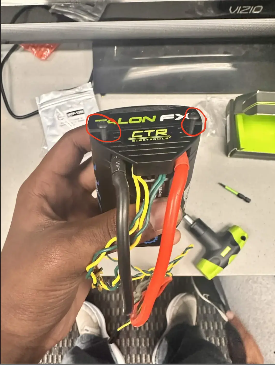
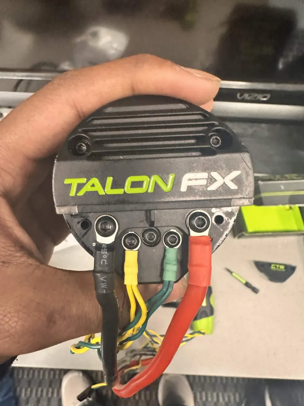
Once you remove the cover, It should look like the image above.
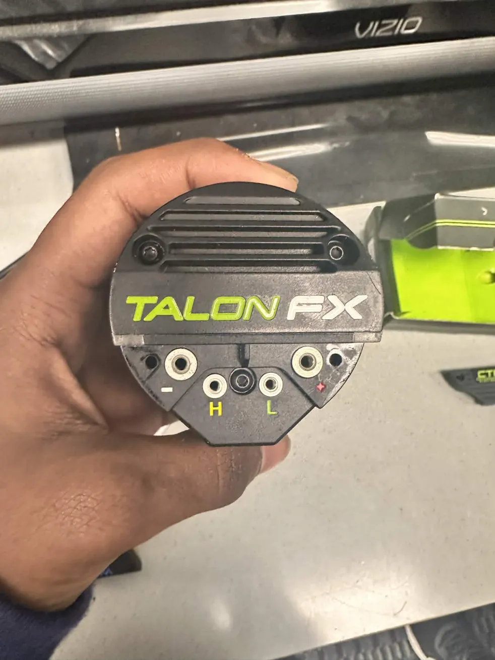
Then unscrew all the screws that clamp the ring terminals for all the wires (CAN and Power), which should look like the image above, 4 empty holes (-, +, H, L).
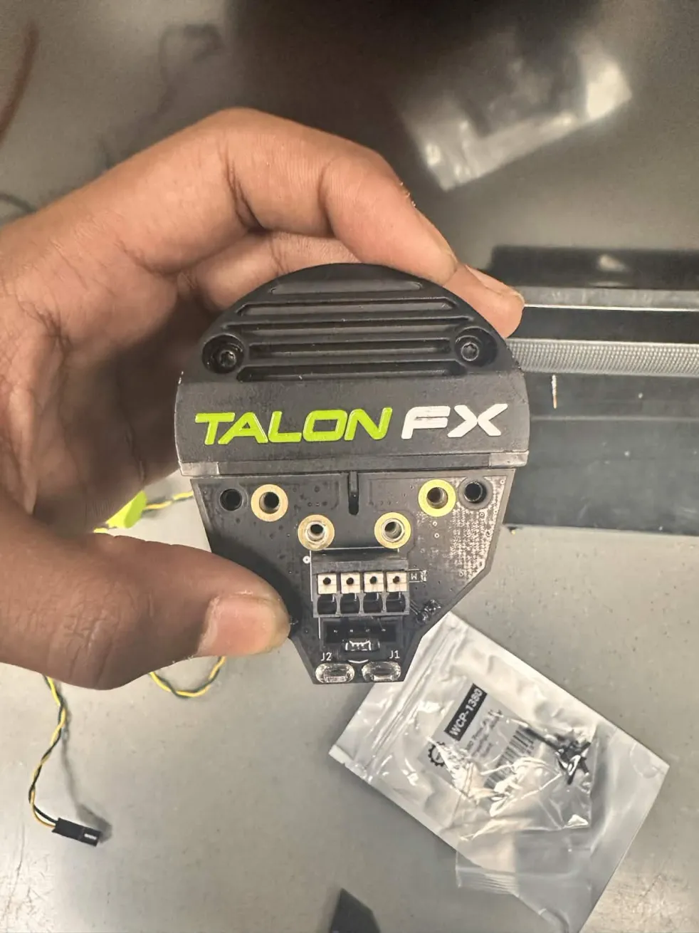
PCB Installation
ALWAYS USE THE SCREWS THAT COME WITH THE PCBS - Anish Mallepally, (2026)
Take the PCB, and align the holes on the PCB onto the holes on the Kraken Motor.
Screw in the holes, and make SURE to use LOCTITE®
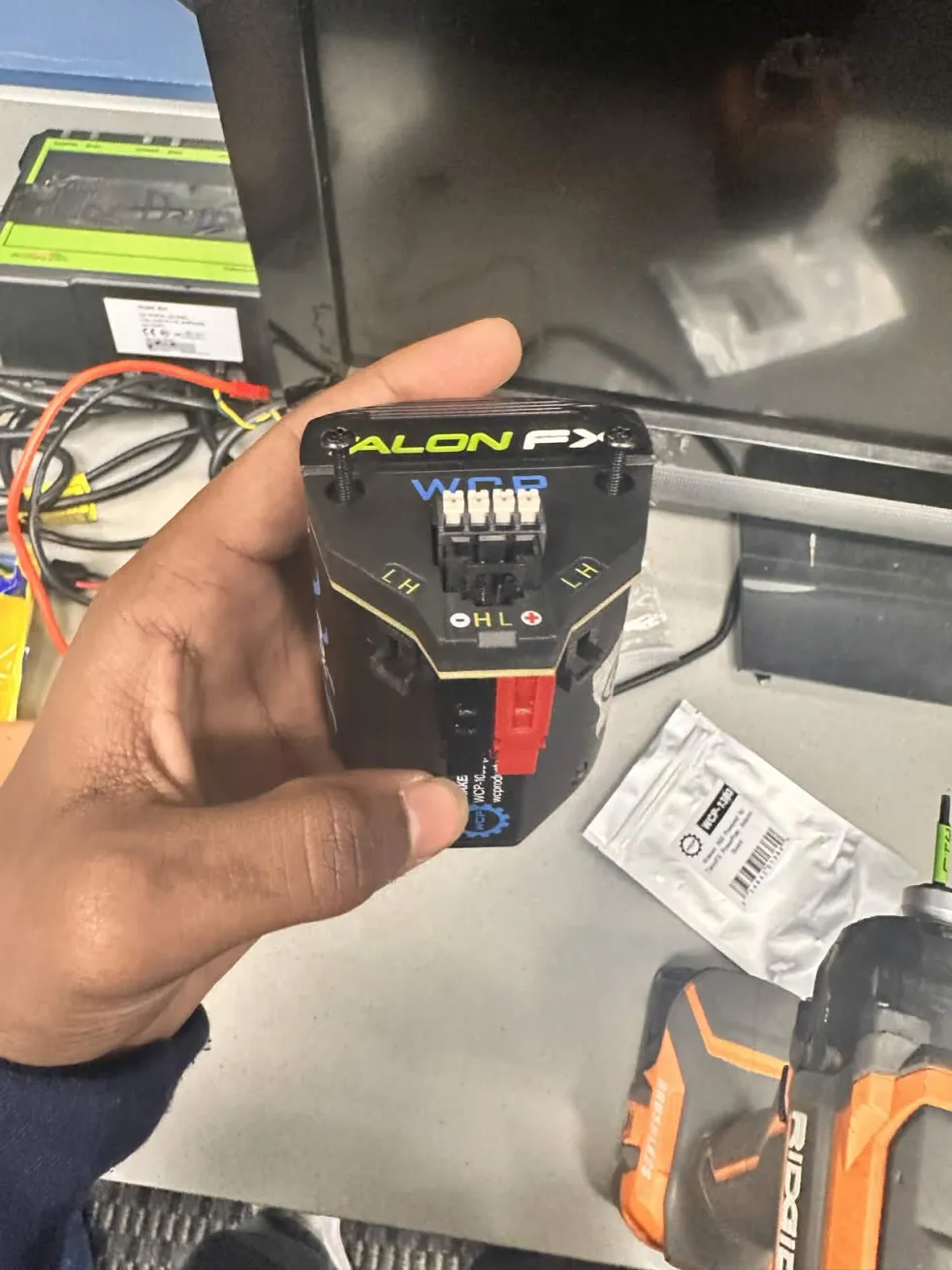
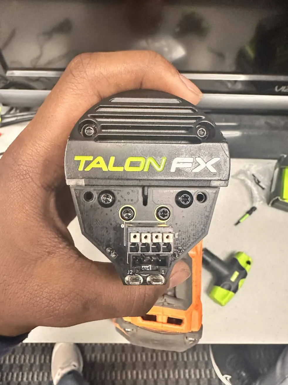
Finally end it off by screwing in the cover, DON'T use LOCTITE® here.
And there you have it, a fully finished TalonFX PowerPole Adapter Board, or a WCP Right Angle Kraken PCB.
MEDIA
Here's an official WCP Tutorial of PCB Installation:
https://youtube.com/shorts/RKLAPSY0UjY?si=c9G2TtTBBfqGsSln
Anish's Tutorial:
Kraken PCB Wiring by Anish