Fabrication


Safety

How to maintain safety throughout your mechanical career.

Safety

Safety Glasses

As a mechanical engineer on the team you will be working in the shop constantly. The shop is a dangerous place for your eyes so in order to preserve your vision use safety glasses.

Particularly safety glasses with the code:

ANSI Z87

There are two types of safety glasses

Over-Prescription Safety Glasses - This is for people who already have prescription glasses who want to wear safety glasses over them.

image.png

Safety Glasses - This is for people without prescription glasses.

image.png

Make sure you do NOT bring black safety glasses to competition as FRC volunteers must be able to clearly see your eyes.

Safety

Clothing and Hair

Appropriate clothing and hair management are essential for maintaining a safe working environment. Loose clothing, jewelry, and unsecured hair can become caught in moving machinery, power tools, and rotating equipment, creating serious hazards.

Clothing Requirements

Students working in the shop must wear clothing that allows them to work safely around tools and machinery.

When working in the shop, don't use gloves unless you are lifting a sharp or heavy object. This is because gloves can get caught on rotating tools.

Hair Requirements

Long hair can easily become caught in rotating tools and machinery.

Why These Rules Matter

Rotating machinery such as drills, saws, motors, and other equipment can quickly pull loose clothing or hair into moving parts. These incidents can occur in fractions of a second and may result in serious injuries.


Safety

Emergency Procedures

The safety of all team members is the highest priority. In the event of an emergency, students should remain calm, notify a mentor or team leader immediately, and follow established safety procedures. No student should attempt to handle a serious emergency alone.

Reporting an Emergency

If an injury, fire, or other emergency occurs:

  1. Stop all work immediately.
  2. Turn off and unplug any operating machinery if it is safe to do so.
  3. Alert nearby students and mentors.
  4. Contact a mentor, teacher, or designated safety captain.
  5. Follow instructions from supervising adults and emergency personnel.

Medical Emergencies

For serious injuries:

For minor injuries:

Fire Emergencies

If a fire occurs:

Battery Emergencies

Robot batteries contain significant stored energy and can become dangerous if damaged.

Chemical Spills

If lubricants, adhesives, cleaning products, or other chemicals spill:

Evacuation Procedures

When instructed to evacuate:

Emergency Equipment Locations

All team members should know the locations of:

After an Incident

Any injury, near miss, equipment failure, or unsafe condition should be reported to a mentor or safety captain. Reporting incidents helps the team improve safety procedures and prevent future accidents.

Calipers

A precise device used for measuring distances from 0-6 inches.

Calipers

How to read the measurment

Digital Calipers

1.Close the jaws of the calipers shut.

2.Click the "Zero" Button on the calipers.

3.Open the jaws and clamp on the part you wish to measure.

4.Tighten the set screw.

5.Read it!
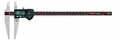
image.png

Dial Calipers

1.Close the jaws of the calipers shut.

2.Unscrew the dial mechanism

3.Rotate the dial until the "0" is matched with the needle

4.Open the jaws and clamp on the part you wish to measure.

5.Tighten the set screw.

6.Read it!
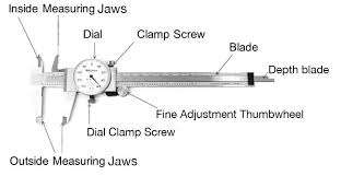
image.png

Informational video on reading dial calipers: Click Here!

Calipers

Different types of measurement

There are 3 different ways to measure with calipers.

1.Measuring the external dimension of a part. To do this clamp on the outside using the external measuring jaws.

EX: Measuring the side lengths of a cube.

Screen Recording 2026-06-24 190052.gif

2.Measuring the internal dimension of a part. To do this clamp on the inside using the internal measuring jaws.

EX: Measuring the slot width or diameter of a circle in a part to confirm tolerances.

image.png

3.Measuring the depth of a part. To do this use the depth gauge at the end of the calipers.

EX: Measuring to the bottom of a threaded hole to pick out the right sized bolt.

image.png

Fasteners

Learn about what holds robots and the field together

Fasteners

Introduction to Fasteners

Fasteners are components used to mechanically join two or more parts together. In FRC, fasteners are essential for building rigid structures, attaching mechanisms, and allowing robots to be serviced and repaired efficiently.

Common types of fasteners include bolts, screws, rivets, nuts, and specialty locking hardware. Choosing the correct fastener affects strength, reliability, and how easily a robot can be maintained.

image.png

Fasteners

Bolt and Nut vs. Tapped Hole

Bolt and Nut

A bolt passes through two or more materials and is secured with a nut on the opposite side.

Advantages:

Disadvantages:

Tapped Hole

A tapped hole has internal threads cut into the material, allowing a screw to thread directly into the part.

Advantages:

Disadvantages:

image.png

Fasteners

Phillips Screws

Phillips screws are cross-head fasteners designed to allow controlled slipping (cam-out) under high torque.

Common driver sizes:

Correct Driver Fit

A proper driver:

Signs of Incorrect Fit

Using the correct driver size is one of the simplest ways to prevent hardware failure.

Fasteners

Washers

Washers are thin discs placed under fastener heads or nuts.

Flat Washers

Lock Washers

Fender Washers

Fasteners

Nylock Nuts

Nylock nuts contain a nylon insert that increases friction on the threads.

Advantages:

Limitations:

Fasteners

Rivets

Rivets are permanent mechanical fasteners used to join materials, especially aluminum.

Common sizes:

Advantages

Limitations

Rivets are commonly used in chassis and sheet metal assemblies.

Fasteners

Threadlocker

When to Use

Use blue threadlocker when:


Polycarbonate Warning

Do not use threadlocker in contact with polycarbonate (Lexan) or other stress-sensitive plastics.

Instead, use:


Application


Key Idea

Threadlocker is a backup for vibration resistance, not a replacement for proper fastener selection or good mechanical design.

Measuring and Marking

Learn how to properly mark materials to be cut.

Measuring and Marking

Introduction to FRC Extrusion

Rectangular aluminum extrusion is used in FRC to build robot frames and structural mechanisms. The strength, stiffness, and weight depend on both size and wall thickness.


Common Extrusion Sizes

1" × 1"

2" × 1"

2" × 2"


Wall Thickness (WCP Options)

West Coast Products (WCP) commonly offers:

Thicker walls increase strength but also add weight.


0.5 Inch Hole Spacing

Many FRC designs use a 0.5 inch grid pattern when drilling extrusion.

This means holes are placed every half inch (0.5", 1.0", 1.5", etc.) to create consistent mounting locations.

This system:


Key Idea

Different extrusion sizes and wall thicknesses control strength and weight, while the 0.5 inch grid system ensures accurate and repeatable assembly.

Measuring and Marking

How to Measure Accurately with a Tape Measure

Accurate measurement is critical in FRC fabrication. Small errors can cause misaligned parts and poor assembly fit.


Reference Edge (Most Important Rule)

Always measure from a consistent, known reference point. For FRC extrusion, this should be the factory-cut end of the tube.

This ensures every measurement starts from a true, flat surface.


Using the Tape Measure


Offset Measurement Method (High-Precision Technique)

For improved accuracy in tight tolerance work, you can use an offset method:

This reduces small errors caused by hook movement or wear.


Using a Speed Square for Marking

A speed square is used to create accurate 90° layout lines.

How to use it:

This ensures:


Common Mistakes


Key Idea

Accuracy comes from using a consistent reference edge and controlling measurement error through either direct reading or a properly applied offset method.

Measuring and Marking

Hole Layout Using a Single Datum (Plates + Center Punching)

Accurate hole placement in FRC depends on using a consistent datum and properly marking drill locations before cutting.


Using a Datum for Hole Layout

A datum is a fixed reference edge used to measure all features from.

For plates, the best datum is usually:

All hole locations should be measured from this same edge:

Using one datum ensures:


Marking Hole Locations

Once measurements are made:


Center Punching

A center punch is used to lock in the exact drill location before drilling.

Why it is used:

How to use it:


Best Practice Workflow

  1. Choose a single datum edge
  2. Measure all hole positions from that datum
  3. Mark each point clearly
  4. Use a center punch on every hole location
  5. Drill carefully, keeping the bit centered in the punch mark

Key Idea

Good hole accuracy comes from consistent measurement from the same datum and center punching every mark before drilling.

Measuring and Marking

Scribing and Marking Tools

Accurate layout work in FRC depends on clearly marking where cuts and holes will be made. Scribing and marking tools help create precise, repeatable reference lines before drilling or cutting.


Pencil and Marker

Limitations:


Scribe

A scribe is a sharp tool used to scratch fine lines into metal surfaces.

Advantages:

Best use:


Combination Square

A combination square is used to mark straight, perpendicular lines.

Uses:


Speed Square

A speed square is used for quick and accurate right-angle marking.

Uses:


Best Practice


Key Idea

Good fabrication starts with good marking. Scribes and squares turn measurements into accurate, repeatable reference lines that prevent errors during drilling and cutting.

Measuring and Marking

Tolerance and Why ±1/32" Matters


What Is Tolerance?

Tolerance defines how far a part can deviate from its intended dimension while still working correctly.

Example:


Why ±1/32" Matters in FRC

A tolerance of 1/32 inch (0.031") may seem small, but in robotics it can:

Small errors add up when multiple parts depend on each other.


When Tight Tolerances Are Needed

Tight tolerances (like ±1/32") are important when:


When Loose Tolerances Are Acceptable

Looser tolerances are acceptable when:


Best Practice


Key Idea

Tolerance is not just a number—it is what determines whether parts fit together correctly or create assembly problems. In FRC, ±1/32" can be the difference between a smooth assembly and a misaligned mechanism.

Hand Tools

How to use all of the different hand tools in the shop.

Hand Tools

T-Handles and Wrenches

T-handles and wrenches are common hand tools used in FRC for installing and removing fasteners. Choosing the right tool improves speed, safety, and prevents damage to hardware.


T-Handles

T-handles are used with hex (Allen) fasteners and provide better torque control than standard L-shaped hex keys.

Advantages:

Best use in FRC:


Wrenches

Wrenches are used on external hex fasteners such as nuts and bolt heads.

Common types in FRC:

Advantages:


Proper Use


Common Mistakes


Key Idea

T-handles are best for fast, controlled tightening of hex fasteners, while wrenches are essential for nuts and bolts. Using the correct tool protects hardware and improves build quality.

Hand Tools

Ratchets and Sockets

Ratchets and sockets are common hand tools in FRC used for quickly tightening or loosening nuts and bolt heads. They are especially useful in tight spaces where a wrench cannot fully rotate.


Ratchet

A ratchet is a handle tool that allows continuous tightening or loosening without removing the tool from the fastener.

Advantages:


Sockets

Sockets attach to the ratchet and fit over the fastener.

Types used in FRC:

Key rule:


Proper Use


Common Mistakes


Key Idea

Ratchets and sockets make fastener work faster and more efficient, but only when the correct size is used and the tool is properly aligned with the hardware.

Hand Tools

Pliers and Vice Grips

Pliers and vice grips are gripping tools used in FRC for holding, bending, and temporarily securing parts. They are not primary fastening tools, but they are useful for support tasks during assembly.


Pliers

Pliers are hand tools used to grip, bend, or hold small parts.

Common uses in FRC:

Types:


Vice Grips (Locking Pliers)

Vice grips are adjustable pliers that lock into place with high gripping force.

Advantages:

Common uses in FRC:


Proper Use


Common Mistakes


Key Idea

Pliers and vice grips are support tools in FRC. They are best used for holding and adjusting parts, not for replacing proper fastener tools like wrenches or sockets.

Hand Tools

Deburring Tools

Deburring tools are used in FRC fabrication to remove sharp edges (burrs) created after cutting, drilling, or machining metal parts. Proper deburring improves safety, fit, and part durability.


What Is a Burr?

A burr is a sharp or rough edge left behind after:

Burrs can cause:


Deburring Tools

Hand Deburrer

Deburring Bit (in drill)

File or Sanding Tool


Proper Use


Common Mistakes


Key Idea

Deburring is a small step that has a big impact. Removing sharp edges improves safety, ensures proper fastener fit, and increases overall build quality in FRC robots.

Hand Tools

Clamps

Clamps are holding tools used in FRC fabrication to secure parts together during assembly, drilling, or gluing. They act as temporary “extra hands” to keep parts aligned and stable.


Why Clamps Are Used

Clamps help:


Common Types of Clamps in FRC

C-Clamps

Quick-Release (Trigger) Clamps

Bar Clamps


Proper Use


Common Mistakes


Key Idea

Clamps improve accuracy and safety by holding parts in place during fabrication. Proper clamp selection and placement are essential for consistent, high-quality FRC builds.

Drilling

How to drill.

Drilling

Drill Bit Sizes

Selecting the correct drill bit size is important for proper fastener fit, tapping, and hole accuracy in FRC fabrication.


Common FRC Drill Bit Sizes

Drill Bit Common Use
#43 (0.089") Tap drill for 4-40
#36 (0.106") Tap drill for 6-32
#21 (0.159") Tap drill for 10-32
#7 (0.201") Tap drill for 1/4-20
1/8" Rivets and small hardware
3/16" Large rivets
13/64" Clearance hole for 10-32
17/64" Clearance hole for 1/4-20

Tap Drill vs. Clearance Drill

Tap Drill

A tap drill creates the correct size hole for cutting threads with a tap.

Example:

Clearance Drill

A clearance hole allows a fastener to pass through freely.

Example:


Best Practices


Common Mistakes


Key Idea

Using the correct drill bit size ensures proper fastener fit, accurate hole placement, and reliable assemblies on an FRC robot.

Drilling

Pilot Holes

A pilot hole is a small hole drilled before the final hole size. Pilot holes improve accuracy and make larger holes easier to drill.


Why Use a Pilot Hole?

Pilot holes help:


When to Use Pilot Holes

Pilot holes are especially useful when:

Small holes, such as rivet holes, often do not require a pilot hole.


Typical Process

  1. Mark the hole location.
  2. Center punch the hole.
  3. Drill a small pilot hole (such as 1/8").
  4. Drill the final hole size.

Best Practices


Key Idea

Pilot holes improve drilling accuracy and make larger holes easier to produce. Taking the extra step can prevent misplaced holes and improve part quality.

Drilling

Drill Presses vs. Hand Drills

Both drill presses and hand drills are commonly used in FRC fabrication. Choosing the correct tool depends on the accuracy, size, and location of the hole.


Drill Press

A drill press holds the drill bit perpendicular to the material and provides precise control.

Advantages:

Best for:


Hand Drill

A hand drill is portable and can be brought directly to the workpiece.

Advantages:

Best for:


Safety


Key Idea

Use a drill press when accuracy is most important and a hand drill when portability and accessibility are needed. The right tool depends on the job.

Drilling

Proper Feed Pressure and Speed

Proper feed pressure and drill speed are important for producing clean holes, extending tool life, and improving safety.


Feed Pressure

Feed pressure is the amount of force applied while drilling.

Too much pressure can:

Too little pressure can:


Drill Speed

Different materials and bit sizes require different speeds.

If the drill bit becomes extremely hot or produces poor chips, adjust the speed or feed pressure.


Signs of Proper Drilling


Common Mistakes


Key Idea

Use steady pressure and the proper drill speed for the material and bit size. Let the drill bit cut the material rather than forcing it through.

Riveting

A more advanced method of mating parts.

Riveting

Why FRC Teams Use Rivets

Rivets are permanent mechanical fasteners commonly used in FRC for joining thin materials such as sheet metal and gussets to structural members.


What Is a Rivet?

A rivet is a fastener that permanently joins two or more materials by expanding inside a drilled hole. Once installed, it cannot be removed without drilling it out.


Why FRC Teams Use Rivets

FRC teams use rivets because they are:


Common Applications

Rivets are often used for:


Installation Tool

Rivets are installed using a hand rivet gun or pneumatic rivet tool, which pulls the mandrel and expands the rivet body inside the hole.


Limitations


Best Practice


Key Idea

Rivets are a fast, lightweight, and vibration-resistant fastening method, making them ideal for sheet metal and non-adjustable structural joints in FRC robots.

Riveting

Blind Rivets

Blind rivets (also called “pop rivets”) are a common fastening method in FRC used to join materials when you only have access to one side of the joint.


What Is a Blind Rivet?

A blind rivet is a fastener that is installed from one side of the material using a rivet gun. When set, it expands and locks the materials together permanently.


Why They Are Called “Blind”

They are called blind rivets because you do not need access to the back side of the joint during installation.

This is useful when:


Why FRC Teams Use Them

Blind rivets are popular in FRC because they are:


Common Uses


Installation Tool

Blind rivets are installed using a:

The tool pulls a mandrel through the rivet, expanding it and locking it in place.


Limitations


Best Practice


Key Idea

Blind rivets are used when access is limited but a fast, lightweight, and secure fastening method is needed in FRC fabrication.

Riveting

Sizes and Grip Range

Blind rivets are a common fastening method in FRC used to join sheet metal, gussets, and extrusion when access is only available from one side. Two important factors when selecting rivets are size and grip range.


3/16" Rivets (Common FRC Size)

3/16" rivets are larger diameter blind rivets used when a stronger joint is needed.

Best uses:

Requirements:

Tradeoffs:


Grip Range

Grip range is the total thickness of material a rivet can properly clamp.

If grip range is incorrect:

Correct grip range ensures:


Best Practice


Key Idea

In FRC, 3/16" rivets are used for stronger structural joints, but only work correctly when paired with the proper grip range for the material thickness.

Riveting

Rivet Guns

A rivet gun is a tool used to install blind rivets in FRC. It works by pulling a mandrel through the rivet body, expanding it and locking materials together permanently.


Types of Rivet Guns

Hand Rivet Gun

Pneumatic Rivet Gun


How a Rivet Gun Works

  1. Insert rivet into the drilled hole
  2. Place rivet gun nose onto the mandrel
  3. Squeeze or activate the tool
  4. The mandrel is pulled, expanding the rivet
  5. The mandrel snaps off once fully set

Proper Use


Common Mistakes


Maintenance


Key Idea

Rivet guns turn a simple blind rivet into a strong, permanent joint. Proper alignment, correct sizing, and full actuation are essential for reliable FRC construction.

Riveting

Common Mistakes

Rivets are simple to install, but small errors can lead to weak joints, misalignment, or failed assemblies in FRC robots.


Incorrect Hole Size

Always match the drilled hole size to the rivet specification.


Wrong Grip Range

Grip range must match the total material thickness.


Poor Alignment


Not Deburring Holes


Incomplete Setting


Overusing Rivets


Key Idea

Strong riveted joints depend on correct hole size, proper grip range, clean installation, and good alignment. Most rivet failures come from small setup mistakes rather than the rivet itself.

Tapping Threads

How to make the threads for bolts to tap into.

Tapping Threads

General Overview

A tapped hole is a drilled hole that has internal threads cut into it so a screw or bolt can be directly threaded into the material without using a nut.


How It Works

  1. A hole is drilled to a specific size (called a tap drill size)
  2. A tool called a tap is used to cut threads inside the hole
  3. A screw or bolt can then be threaded directly into the material

Why FRC Teams Use Tapped Holes

Tapped holes are useful because they:


Common Applications


Limitations


Best Practice


Key Idea

A tapped hole allows a screw to thread directly into a material, making it useful for compact and lightweight FRC designs, but it must be used carefully to avoid stripping threads.

Tapping Threads

Tap Drill Hole Sizes

Page — Tap Drill Hole Sizes (10-32 and 1/4-20)

Before tapping a hole, the correct drill bit diameter must be used. The tap drill is slightly smaller than the final thread size so the tap can cut threads into the material properly.


10-32 Tap Holes

For a 10-32 thread, the correct tap drill size is:

This size provides:


1/4-20 Tap Holes

For a 1/4-20 thread, the correct tap drill size is:

This size provides:


Why Correct Hole Size Matters

Using the wrong tap drill size can cause:


Best Practice


Key Idea

Tap drill size determines thread strength and reliability. In FRC, #21 for 10-32 and #7 for 1/4-20 are standard sizes that ensure strong, consistent threaded holes.

Tapping Threads

Using a Hand Tap

A hand tap is a tool used to cut internal threads into a drilled hole so that a screw or bolt can be directly fastened into material such as aluminum.


Before Tapping


How to Use a Hand Tap

  1. Insert the tap into a tap handle
  2. Align the tap perpendicular to the hole
  3. Apply gentle downward pressure and begin turning clockwise
  4. After 1–2 turns, continue turning slowly with steady pressure
  5. Every few turns, reverse slightly to break chips
  6. Continue until the desired thread depth is reached

Key Technique


Common Mistakes


Key Idea

A hand tap must be started carefully and kept straight. Most tap failures come from misalignment or forcing the tool instead of allowing it to cut gradually.

Tapping Threads

Cutting Fluid

Cutting fluid is a lubricant used during drilling and tapping to reduce friction and heat.


Why It’s Used


When to Use It


How to Use It


Key Idea

Cutting fluid makes drilling and tapping easier and safer by reducing heat and friction, especially in aluminum.

Tapping Threads

Preventing Broken Taps (Conclusion)

Preventing broken taps comes down to control, preparation, and patience.


Key Habits


What to Avoid


Final Idea

Most tap failures are caused by technique, not the material. Careful alignment, steady motion, and chip control make tapping reliable and safe in FRC fabrication.

Materials

Learn about all the different materials you will encounter in FRC.

Materials

Aluminum

Aluminum is one of the most important materials in FRC. Different aluminum series have very different strengths, machining behavior, and real-world use in robot components.


6061-T6 Aluminum

6061-T6 is the most common structural extrusion material in FRC.

Properties:

Typical use:


5052 Aluminum

5052 is most commonly used as sheet metal stock in FRC.

Properties:

Typical use:


7000 Series Aluminum (e.g., 7075)

7000 series aluminum is a high-strength aerospace-grade material that is significantly stronger than 6061.

Properties:

Typical use:


7000 Series in COTS FRC Components (WCP and Similar Vendors)

In FRC, 7000 series aluminum (commonly 7075) is often used in COTS (Commercial Off-The-Shelf) components, especially from vendors like West Coast Products.

Instead of teams machining it themselves, it is typically found in:

Why vendors use it:


6061 vs 5052 vs 7000 Series


Key Idea

Most FRC robots are built from 6061 extrusion and 5052 sheet, but 7000 series aluminum appears frequently in COTS components from vendors like West Coast Products because it enables stronger, lighter, and more compact high-performance parts.

Materials

Steel

Steel is a strong, heavy metal sometimes used in FRC for high-strength or wear-resistant applications. While aluminum is more common, steel is chosen when extra strength or durability is required.


Why FRC Teams Use Steel

Steel is used because it:


Common Types of Steel in FRC

Mild Steel

Hardened Steel


Common Applications


Limitations


Key Idea

Steel is used in FRC when strength and durability matter more than weight. It is most commonly found in shafts, fasteners, and high-load components rather than full structural frames.

Materials

Polycarbonate

Polycarbonate (often called “polycarb”) is a tough, transparent plastic widely used in FRC for protective and structural sheet applications.


Why FRC Teams Use Polycarbonate

Polycarbonate is used because it:


Common Applications


Properties to Know


Important Handling Notes


Key Idea

Polycarbonate is a strong, impact-resistant plastic that is ideal for protective and lightweight structures in FRC. Proper drilling and fastening techniques are important to prevent cracking and extend part life.

Materials

SRPP (Glass-Filled Polypropylene)

SRPP is a glass-filled polypropylene sheet material commonly used in FRC, often supplied or popularized through vendors like West Coast Products.


What It Is

SRPP is a reinforced plastic made from:

This combination makes it significantly stronger and stiffer than standard plastic sheet.


Why FRC Teams Use SRPP

SRPP is used because it:


Common Applications


Manufacturing Notes


Limitations


Key Idea

SRPP is a lightweight, glass-filled plastic sheet material used in FRC as a strong alternative to aluminum plates in lower-to-medium load applications, especially where weight savings matter.

Materials

Plywood

Plywood is a layered wood composite made by pressing thin sheets of wood veneer together with alternating grain directions. This structure gives it strength and resistance to cracking compared to solid wood.


Why FRC Teams Use It

Plywood is used because it:


Common Use in FRC

Plywood is primarily used as bumper backing, where it:


Material Notes


Limitations


Key Idea

Plywood is a strong, low-cost composite material used in FRC for structural support in bumper systems, where rigidity and durability are more important than weight savings.

Materials

Common 3D Printer Filaments

3D printing filaments in FRC form a spectrum of materials that trade off between ease of printing, stiffness, toughness, and flexibility. Understanding how they relate helps teams choose the right material for each application instead of defaulting to one.


The “Spectrum” of Filaments

You can think of common filaments as a progression:

As you move right:


Rigid vs. Tough vs. Flexible

PLA (Rigid, easy, brittle)


PETG (Tough, slightly flexible)


ABS (Tough + heat resistant)


Nylon (Very tough, wear-resistant, flexible)


TPU (Flexible, elastic)


How They Compare in Use


Key Relationship Idea

These filaments are not separate choices—they form a progression from rigid and easy (PLA) to tough (Nylon) to flexible (TPU). Most FRC teams use a mix depending on whether the part needs accuracy, strength, wear resistance, or compliance.

Materials

When to use which material

Each material used in FRC has distinct mechanical and manufacturing properties that determine how it behaves under load, during machining, and in real-world robot use.


6061-T6 Aluminum


5052 Aluminum


Polycarbonate


SRPP (Glass-Filled Polypropylene)


Steel


Plywood


Key Idea

Each material behaves differently under stress, machining, and impact. Understanding these unique properties allows FRC teams to choose the right material for strength, weight, flexibility, and durability requirements.

Materials

Sheet Thickness

Sheet materials in FRC come in standard thickness increments. These increments strongly affect stiffness, weight, and how parts behave under load.


Common Sheet Thickness Increments

Most sheet materials (aluminum, polycarbonate, plastics) are typically available in:

These standard sizes are what most FRC designs are based on.


How Thickness Affects Strength

1/16"


1/8"


3/16"


1/4"


3/8"


1/2"


Why Teams Pocket Parts


Key Idea

FRC sheet design is about balancing standard thickness options with strategic material removal. Pocketing helps teams keep strength where needed while eliminating excess weight.

FRC Hardware Standards

Learn about all the hardware a typical FRC robot consists of.

FRC Hardware Standards

10-32 Hardware

10-32 is the most common fastener size used in FRC. It provides a good balance of strength, weight, and ease of use, making it suitable for many robot assemblies.


What Does 10-32 Mean?

This makes 10-32 a fine-thread fastener that provides good holding strength in aluminum.


Common Hardware

10-32 hardware includes:


Common Lengths

Typical lengths used in FRC include:

The correct length should allow full thread engagement without excessive exposed threads.


Typical Tools


Why FRC Teams Use It


Key Idea

10-32 hardware is the standard fastener system for many FRC robots because it provides reliable strength while remaining compact and easy to work with.

FRC Hardware Standards

1/4-20 Hardware

1/4-20 hardware is commonly used in FRC for high-load applications where additional strength is needed. The larger diameter provides greater thread engagement and improved resistance to stripping.


What Does 1/4-20 Mean?

This makes 1/4-20 a coarse-thread fastener that is durable and well-suited for structural applications.


Common Hardware

1/4-20 hardware includes:


Common Lengths

Typical lengths used in FRC include:

The correct length should allow full thread engagement without excessive exposed threads.


Typical Tools


Why FRC Teams Use It


Key Idea

1/4-20 hardware is used when additional strength and durability are needed. Its larger size makes it ideal for high-load joints and structural connections.

FRC Hardware Standards

Shafts

Shafts are rotating elements used to transmit torque through a robot’s mechanisms. In FRC, different shaft geometries are used depending on how securely components must transfer motion and how much load the system experiences.


Common Shaft Types

1/2" Hex Shaft


3/8" Hex Shaft


1/2" Round Shaft


Spline XL Shaft System

Spline XL is a high-torque shafting system used in FRC for demanding applications.

Key Features:

Why Teams Use It:


How They Relate

As load requirements increase, teams typically move from round → smaller hex → 1/2" hex → spline-based systems.


Common Applications


Key Idea

Shaft selection depends on torque, packaging, and reliability needs. 3/8" hex is a compact option, 1/2" hex is the standard, round shafts require additional retention, and Spline XL is used when maximum torque capacity and durability are required.

FRC Hardware Standards

Bearings and Bushings

Bearings and bushings support rotating shafts and reduce friction between moving parts. They are essential components in nearly every FRC mechanism.


Bearings

Bearings use rolling elements, typically balls, to allow shafts to rotate with very low friction.

Advantages:

Common FRC uses:


Bushings

Bushings use a smooth surface that the shaft slides against rather than rolling elements.

Advantages:

Common FRC uses:


Common Bearing Sizes

Typical FRC bearings include:

Bearings are often press-fit into plates, tubes, or bearing blocks.


Bearing vs. Bushing


Key Idea

Bearings provide smooth, efficient rotation for most FRC mechanisms, while bushings offer a simple solution for lower-speed or lower-load applications. Choosing the correct support method improves reliability and reduces wear.

FRC Hardware Standards

Plastic Washers

Plastic washers are low-friction spacing components commonly used in FRC to reduce wear, prevent metal-on-metal contact, and fine-tune alignment in assemblies. West Coast Products (WCP) offers commonly used versions designed for FRC mechanisms.


What They Do

Plastic washers are placed between moving or clamped components to:


Why Teams Use Them

Compared to metal washers, plastic washers:


Common Applications


Material Properties

Plastic washers (such as those from WCP) typically:


Best Practices


Key Idea

Plastic washers are used in FRC to reduce friction and wear while improving spacing accuracy in moving assemblies, making mechanisms smoother and more reliable over time.

FRC Hardware Standards

Standoffs

Standoffs are rigid spacers with threaded ends or through-holes used to separate and support two parallel components at a fixed distance. They are commonly used in FRC to build compact, lightweight assemblies.


What They Do

Standoffs:


Common Types


Common Applications


Materials

Aluminum is preferred for most mechanical applications due to its strength-to-weight ratio.


Best Practices


Key Idea

Standoffs create precise, rigid spacing between components, allowing FRC teams to build compact and organized assemblies while maintaining strength and alignment.

FRC Hardware Standards

Gussets

Gussets are flat structural plates used to reinforce joints between two or more components, typically at corners or intersections of extrusion in FRC robots.


Purpose

Gussets:


Custom Gussets

Custom gussets are designed by teams and usually cut from sheet material.

Common materials:

Characteristics:


Vendor Gussets (WCP and Similar Suppliers)

Vendor gussets are pre-designed and pre-cut parts from suppliers such as West Coast Products.

Characteristics:

Typical features:


When to Use Each


Key Idea

Gussets reinforce structural joints in FRC robots. Custom gussets provide maximum design flexibility, while vendor gussets offer fast, reliable, and standardized solutions for common structural connections.