# Simulation
This chapter details how to use simulation effectively to develop code without a physical robot, or to aid in tuning with a physical robot.
# Using CAD in AdvantageScope
## Overview
Simulation is very important for YETI, allowing us to test and develop code without a physical robot. Being able to use the CAD created by our team members simulates the actual hardware and can be used to troubleshoot more precisely. The documentation AdvantageScope provides is extremely thorough and it’s always recommended to read the source material. Much of the information found on this page is derived from [these docs](https://docs.advantagescope.org/more-features/custom-assets/#3d-robot-models).
## Exporting from SolidWorks
In order to accurately simulate the many moving parts of a robot, the files themselves must be separate. Anything that is an “[articulated component](https://docs.advantagescope.org/tab-reference/3d-field/#3d-components)”, that provides a degree of freedom and moves independently, such as an elevator, arm, or wrist should be in its own file, and exported as such.
The settings to properly export a component with color are shown below:
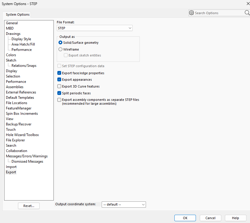
## Converting to .glb
AdvantageScope uses .glb files for 3D models, and while SolidWorks can export CAD files in that format, the files are often very large and we prefer to first export as STEP and later convert to .glb.
A STEP by STEP :) tutorial for conversion using the application CAD Assistant can be found [here](https://docs.advantagescope.org/more-features/gltf-convert/#converting-step-to-gltf).
## Configuring the Robot
Configuring your individual components is arguably the most important step, as without doing so you just have a bunch of floating arms and a robot that looks vaguely like a Roomba.
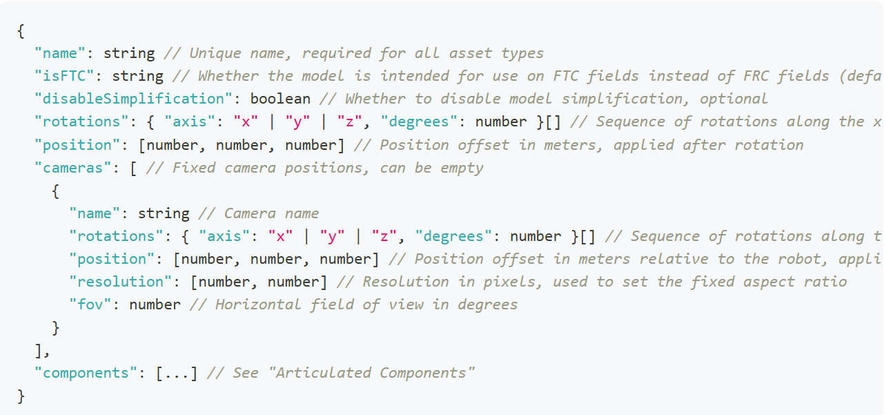
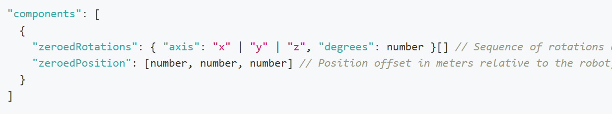
Below is the format the config.json file should be in:
[](https://wiki.yetirobotics.org/uploads/images/gallery/2025-06/J1timage.png)
[](https://wiki.yetirobotics.org/uploads/images/gallery/2025-06/Cesimage.png)
Do note that anything in the above format that looks like {something something} \[\] is a list where you add elements in the format of {something something}. Namely, the rotations are a sequence that contains only the axes that require rotation.
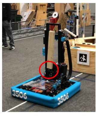
To configure the components, the exact measurements for the positions of the components are needed.
Here, the zeroed position of an arm (portrayed as a wooden block) is circled in red.
[](https://wiki.yetirobotics.org/uploads/images/gallery/2025-06/Au3image.png)
First, the model of the arm must be rotated until it is oriented correctly relative to the robot. If the arm in the file were “lying down”, it would have to be rotated along the y axis, 90 degrees to make it point upwards.
[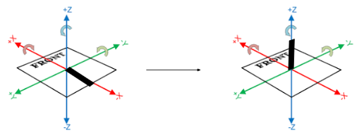](https://wiki.yetirobotics.org/uploads/images/gallery/2025-06/B1Ximage.png)
"zeroedRotations": \[ { "axis": "y", "degrees": 90} \]
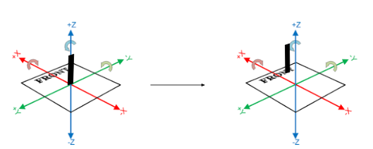
Using the actual measurements of the robot, whether in real life or from CAD, you can fill out the “zeroedPosition” list. In this case, the joint at which the arm is connected is x centimeters back from the center of the robot (on the x axis) and z centimeters up from the base (on the z axis). It’s already centered with the robot “left and right” so there is no translation needed on the y axis.
[](https://wiki.yetirobotics.org/uploads/images/gallery/2025-06/AoAimage.png)
"zeroedPositions": \[x, 0, z\]
The component for the arm would be
{
"zeroedRotations": \[
{ "axis": "y", "degrees": 90}
\],
"zeroedPosition": \[x,0,z\]
}
This process should be repeated for all other components, and the file names of each component model should be “model\_INDEX.glb”, the index being that of the component in the array “components” beginning at 0.
A video for all this can be found in the docs for Custom Assets in AdvantageScope that were linked at the beginning of this page: [here](https://docs.advantagescope.org/more-features/custom-assets/#video-tutorial).
# Simulating Beluga in the Sim Sandbox
## Setting Up AdvantageScope
To get AdvantageScope, you can download the version for your operating system here: [https://github.com/Mechanical-Advantage/AdvantageScope/releases](https://github.com/Mechanical-Advantage/AdvantageScope/releases)
Then, follow the installer instructions for your system. Please install the latest **stable** release, and not the beta versions.
After opening AdvantageScope, go to Help > Show Assets Folder. Note that if you are using the **alpha** release of AdvantageScope for Systemcore testing purposes, you will need to go under the AdvantageScope menu instead of Help. This will show you in Finder/File Explorer where the path of your assets folder is. You will need to know this for the next steps.
## Getting Beluga in AdvantageScope
To get Beluga into AdvantageScope, download this .zip file from the YETI Shared Drive: [https://drive.google.com/file/d/1L-IlO6yLEO3EWTT7hQ3TDLUFpgTqMgc7/view?usp=drive\_link](https://drive.google.com/file/d/1L-IlO6yLEO3EWTT7hQ3TDLUFpgTqMgc7/view?usp=drive_link)
If you are not part of the shared drive, please contact Mrs. Iaiela Dumitrescu to be added.
Extract the `Robot_Beluga` folder, and copy this into your assets folder that you found in the previous steps.
You will use Beluga when using the Sim Sandbox.
## Getting Started with the Sim Sandbox
To get started, make sure you have `git` installed. If not, get it from this link for your operating system: [https://git-scm.com/downloads](https://git-scm.com/downloads)
Go to the sim-sandbox repository on the YETI GitHub, or use this link: [https://github.com/yeti-robotics/sim-sandbox](https://github.com/yeti-robotics/sim-sandbox). Then, click on the "Use this template" button in the top right hand corner. Click "Create new repository," and pick a name for it. Make sure to check the box that includes all branches! This will create your own repository with all of the template files to start.
Next, open up IntelliJ and head over to File > New > Project from Version Control. Select the Git option, and then paste in the URL of your repository, which you'd get from pressing the green "Code" button when you go to the repository in your browser, and copying the URL that you find in the little dropdown beneath it. It should look something like this
```shell
https://github.com/YOUR_GITHUB_USERNAME/REPO_NAME.git
```
YOUR\_GITHUB\_USERNAME should be replaced with your GitHub username, and the REPO\_NAME should be replaced with whatever you decided to name the repository when creating it. Once you hit the "Clone" button, this will download everything onto your device.
Open up the project folder in IntelliJ. Then, you can start up your development work as normal by letting Gradle download the dependencies. Afterwards, go to the Gradle menu, and go under the tasks in the `other` folder. You should then find the `simulateJava` task. Run that task to open the simulator window.
## Connecting the Simulator to AdvantageScope
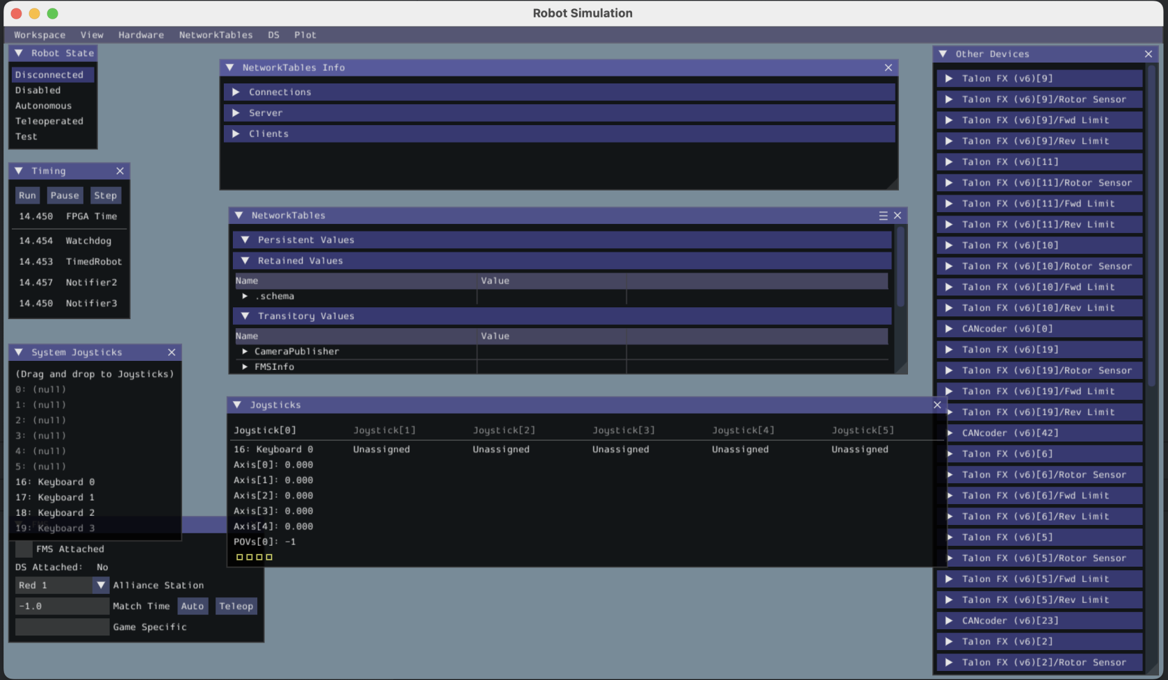
Now that you've opened the simulator, let's start by configuring it. You're going to see an interface that looks something like this:
[](https://wiki.yetirobotics.org/uploads/images/gallery/2025-07/Z3oimage.png)
Let's connect our keyboard to the joystick port so we can drive the robot in simulation later. Under System Joysticks, drag Keyboard 0 on top of Joystick 0. Mine has already been configured as seen in the picture above, but you will need to do that on first launch.
Next, let's enable the robot. Under Robot State, hit the Teleoperated button.
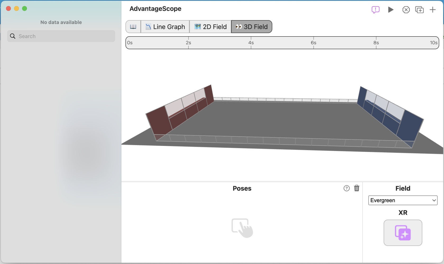
Now, let's go back to AdvantageScope. It'll look something like this on first installation:
[](https://wiki.yetirobotics.org/uploads/images/gallery/2025-07/fnZimage.png)
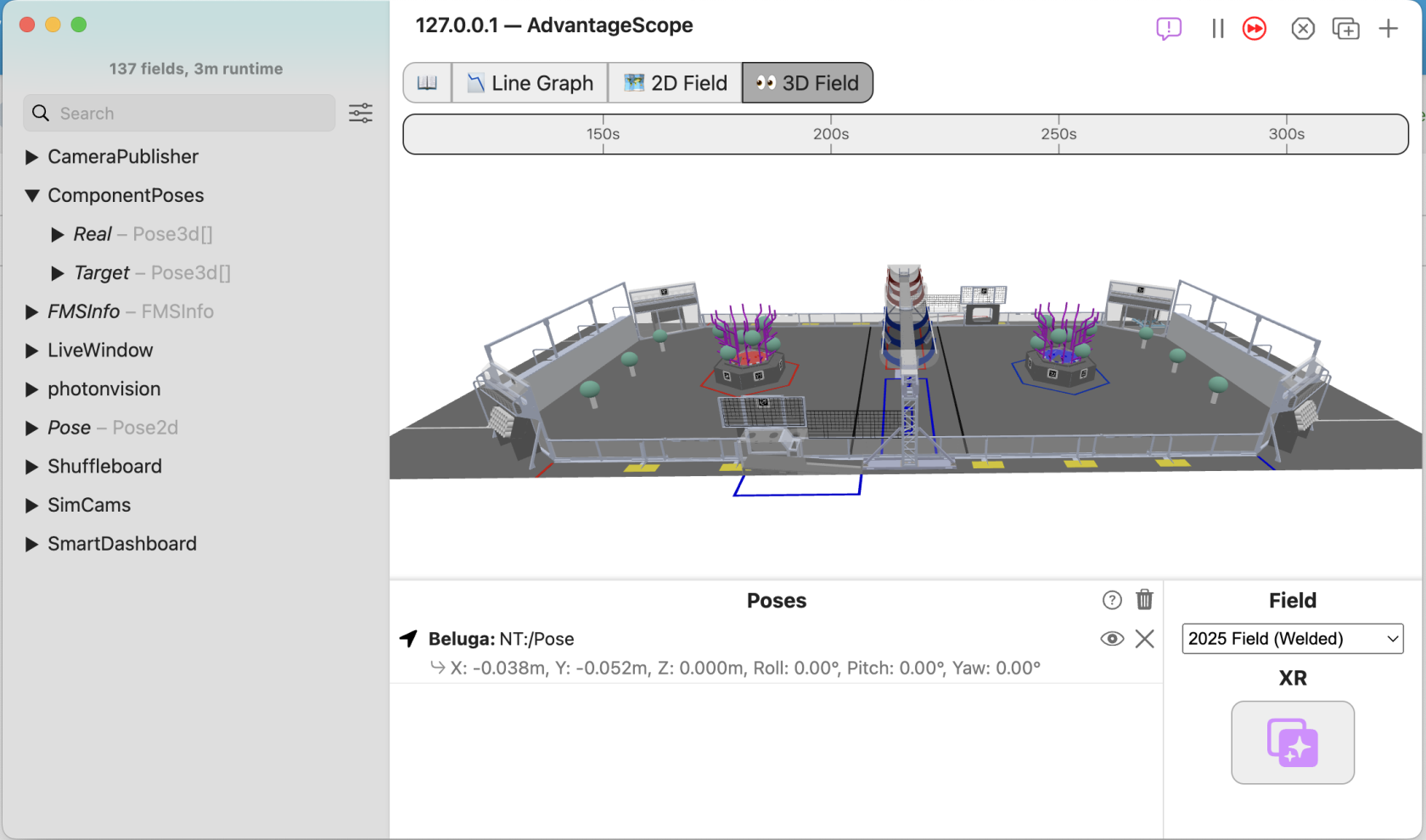
This isn't the right field. Let's change that! Under Field, click the dropdown that currently is Evergreen. Change the field to 2025 Field (Welded). That looks better! Now, if you're a Windows user, press `Ctrl + Shift + K` to connect the simulator to AdvantageScope. If you're a Mac user, press `Cmd + Shift + K` to connect the simulator to AdvantageScope. Your window should now look something like this:
[](https://wiki.yetirobotics.org/uploads/images/gallery/2025-07/Kmoimage.png)
Now, we're missing the robot. Grab the `Pose - Pose2d` object and drag it into the Poses area underneath the 3D field. You should now see something like this:
[](https://wiki.yetirobotics.org/uploads/images/gallery/2025-07/l5Limage.png)
Hold up. This isn't our robot. Let's change that! Right click on 2025 Kitbot and select Beluga instead from the dropdown menu. That's better. Now, we need to add Beluga's components, like the elevator, arm, and wrist. Open up the ComponentPoses dropdown in the sidebar. You should see 2 different items, Real, and Target. It'll look something like this:
[](https://wiki.yetirobotics.org/uploads/images/gallery/2025-07/3wgimage.png)
Now, drag and drop the Real object on top of Beluga. This should look something like this afterward:
[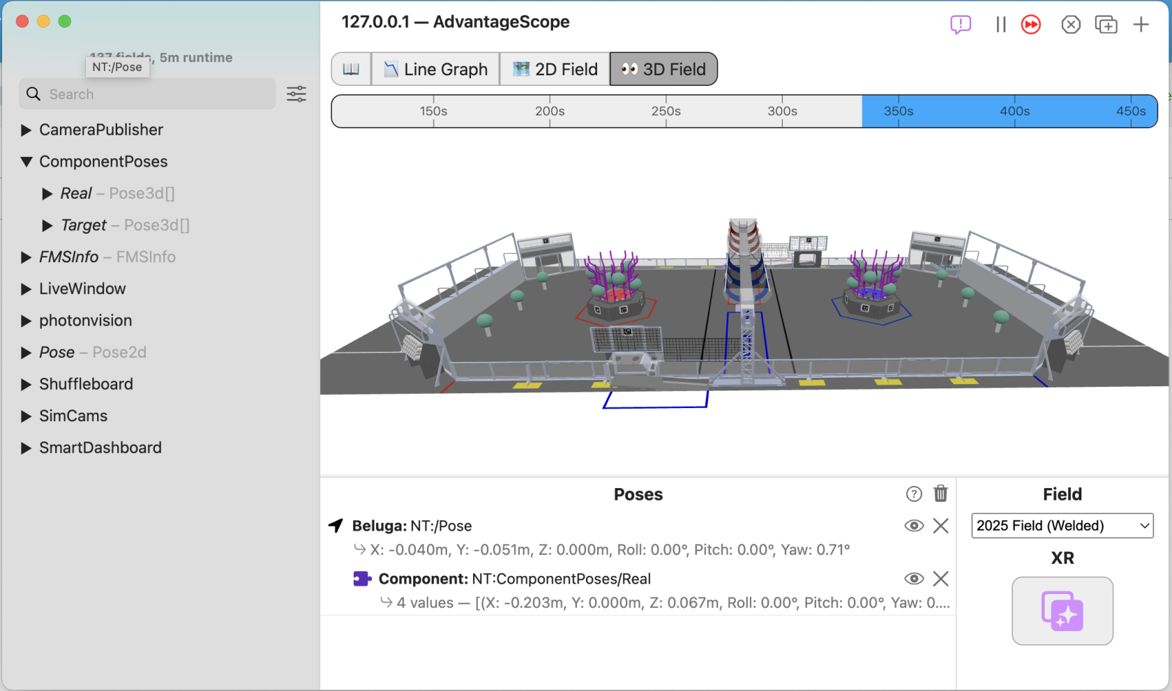](https://wiki.yetirobotics.org/uploads/images/gallery/2025-07/kZ5image.png)
That's it! You now have Beluga on your field. Finally, let's get the robot driving around the field!
## Driving Beluga in Simulation
Go back to your simulation window. Now, you can use the WASD keys on your keyboard to start driving Beluga around. You'll see the robot move on the field. You will need to keep the simulation window in focus when driving the robot around. The best way to do this is by dragging the simulation window to the bottom of the screen, just keeping the title bar in frame so you have something to click to keep it in focus, and then keeping AdvantageScope up top. It'll look something like this:
[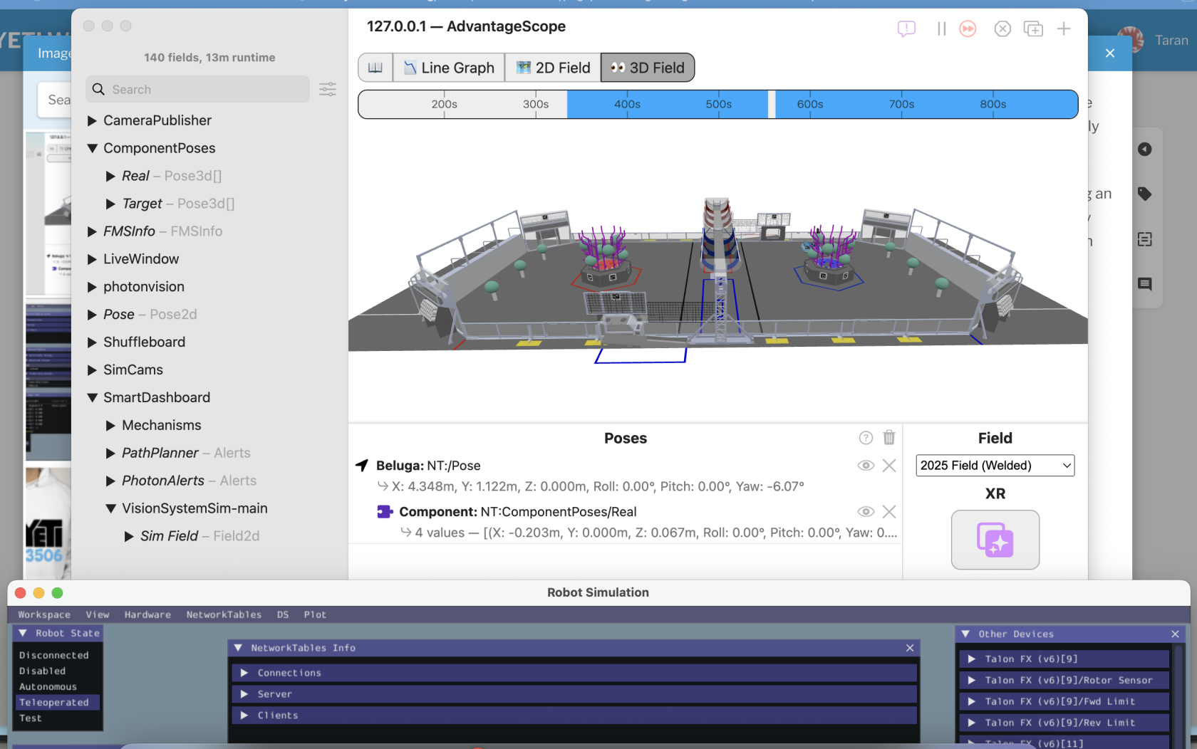](https://wiki.yetirobotics.org/uploads/images/gallery/2025-07/Fguimage.png)
That's it! Now you have a robot driving around in simulation! If you have any questions, feel free to reach out in the Programming channel on Discord. There's always someone around to help you out! After setting this sandbox up, try and code out some of the mechanism commands, like for the elevator, arm, and wrist. Good luck!