Robot Software
Roadmaps, guides, and getting started with what you need to know to effectively program robots on YETI
- Getting Started with Robot Development
- What you need to install
- Learning Robot Code
- Common Command Functions
- Resources
- Intelligently using IntelliJ
- Getting started with a Romi
- Configuring a Robot
- Setting steer offsets for a Mk 4i drivetrain
- Setting the magnet offset for a CANcoder
- Flashing a Radio
- Testing Robot Code
- Setting up Motors
- Re-zero code for drivetrains
- Setting up a new robot (Roborio)
- Gitting Good at Git
- Tools of the Trade
- Tunes for the Road
- Plotting and Scheming
- Key Terms with Tuning
- Tuning a CANrange
- Position Tuning with MotionMagicTorqueCurrentFOC
- Velocity Tuning with MotionMagicVelocityTorqueCurrentFOC
- Shooting Our Shot
- Calibration and Cows
- Autonomous Adventures
- Simulation
- Tips for Comp/Pit Crew/Drive Team
- Taking Advantage Kit
- Upgrading Repositories
Getting Started with Robot Development
This chapter details what software you need to install to write software for our robots provides starting points for learning on your own.
What you need to install
Git
Git is a popular version control system (VCS) for developing software. If you are interested in becoming a Software Engineer or writing code in general, learning to use git is an extremely important skill. You can download git here. When installing, just choose all the default recommended options.
We use GitHub to host and collaborate on our software projects, so you will need to make a GitHub account on github.com. Once you have an account, post your GitHub username in the #controls channel of our discord and we can add you to our GitHub organization which you can find here along with every software project our team has ever worked on.
WPILib
WPILib is the suite of software, known as a library that we use to actually control the components on the robots. WPILib has their own guide for setting up your development environment, however since their guide is designed for everybody across FRC, it has a lot of information not relevant to our team. Following the guide below should get you set up for developing robot programs for YETI. If you run into any issues in your setup, you can ask questions in the #controls channel of the YETI discord, and check out the WPILib guide as it may have the solution to your problem.
NOTE: This guide is for Windows, macOS, and Linux computers. You will NOT be able to write robot programs with ChromeOS.
Download the latest version of the installer from the WPILib Github. Scroll down to Downloads and download the appropriate installer for your operating system.
Read this if you use a mac
Before installing WPILib, mac users will need to install XCode Command Line Tools. These are tools developed by Apple for C++ development which WPILib requires to run. To do so, open the Terminal app on your mac and run the following command
xcode-select --installYou may need to run this command administrator privileges, in which case run the following command and enter your password when prompted. Note: When typing in your password in the terminal, it will look like nothing is happening, but this is just the terminal version of how websites show dots instead of letters in password fields.
sudo xcode-select --installNext, you need to install the appropriate installer for the processor your mac uses, either an Intel or M series (arm64) chip. If you are unsure which your mac uses, do the following:
- Click the apple logo menu in the top left of your screen
- Click about this mac
- If it says you have an Apple M1/M2/etc. chip or an Apple A18 chip, download the arm64 installer. otherwise download the Intel version
- Open the file you downloaded
- Run the WPILibInstaller
- Click Start
- Choose Everything
- Select the top right option that says Skip and don't use VS Code
Why the option that says not recommended?
Selecting Everything will install all the development tools you need to code an FRC robot. The way you actually use those tools to write your code is up to you. All the other options will install a dedicated instance of VS Code, a very popular code editor that can be used to write just about any kind of program. If you already have VS Code installed, it will still install a new version. This is one reason I do not recommend this path, as it can be confusing what version of VS Code you are using.
The other reason is because here on Yeti, we use IntelliJ to write our robot code. This is because IntelliJ is specifically designed for developing Java programs, and so has many useful features that VS Code lacks out of the box. Additionally, I have found that Java development in VS Code is simply much buggier because it is not specifically designed for it while IntelliJ is.
Install for this User or Install for all Users? (doesn't apply to mac)
If you share your computer with anyone else, for example a parent, you should install for this user. If your computer is just yours, you should install for all users. The reason being is that installing for all users requires administrator privileges, which you may not have if this is not your computer. The difference does not matter too much, but installing for all users may create less problems in the future in terms of other software dependencies or updates.
IntelliJ
Here on YETI, we use IntelliJ to write our robot code. This is because IntelliJ is specifically designed for developing Java programs, and so has many useful features that VS Code lacks out of the box. Additionally, I have found that Java development in VS Code is simply much buggier because it is not specifically designed for it while IntelliJ is.
Install
- Download IntelliJ Community Edition (NOT Ultimate)
- Scroll down a little on this page to get to the community edition install
- Run the installer and install IntelliJ
- Open IntelliJ
- When you open IntelliJ, it will begin processing your workspace. The progress bar is in the bottom left.
Setup
Java
Note that this part requires you to have a Gradle project open at the moment. Read this if you don't have one open.
If you don't have a Gradle project open, you can use YETI's sim-sandbox.
Go to the sim-sandbox repository on the YETI GitHub, or use this link: https://github.com/yeti-robotics/sim-sandbox. Then, click on the "Use this template" button in the top right hand corner. Click "Create new repository," and pick a name for it. Make sure to check the box that includes all branches! This will create your own repository with all of the template files to start.
Next, open up IntelliJ and head over to File > New > Project from Version Control. Select the Git option, and then paste in the URL of your repository, which you'd get from pressing the green "Code" button when you go to the repository in your browser, and copying the URL that you find in the little dropdown beneath it. It should look something like this:
https://github.com/YOUR_GITHUB_USERNAME/REPO_NAME.git
YOUR_GITHUB_USERNAME should be replaced with your GitHub username, and the REPO_NAME should be replaced with whatever you decided to name the repository when creating it. Once you hit the "Clone" button, this will download everything onto your device.
- Open settings
- Expand Build, Execution, and Deployment on the left
- Expand Build Tools
- Select Gradle
- Set Distribution to Wrapper
- If on Mac, follow this:
- In the Gradle JVM dropdown, select Download JDK
- Set Version to 17
- Set Vendor to Amazon Corretto
- Click Download
- If on Windows, follow this:
- In the Gradle JVM dropdown, select Add JDK from Disk
- Navigate to C:\Users\Public\wpilib\(your WPiLib version)\jdk
- Select that jdk folder
- Hit OK
FRC Plugin
- Open settings
- Select Plugins on the left
- Select the Marketplace tab at the top
- Search for and install the FRC plugin
Next steps
You can view a list of additional resources here, including links to learn Java. For a guide for learning robot code, we have a roadmap for the FRC Ladder series here.
If you are interested in getting started developing for a Romi robot to practice robot code, we have a guide for setting that up here.
If you are interested in continuing sim-sandbox development and finishing the full simulation setup, follow this guide.
Learning Robot Code
FRCLadder
FRCLadder provides a series of videos that together serve as a great introduction into robot code. We've selected some below that are particularly relevant to the programming YETI does.
Note: The hardware and APIs available have changed quite a bit since some of these videos were published. However, the concepts and theory behind them remain the same.
Introduction to FRC Programming and Basic Drivetrain Code
How PIDs Work and How to Implement Them
Part 1: Dead Reckoning, Bang Bang, and using kP
Part 2: Using kI and kD
Supplemental: A practical example of tuning a PID loop and how each value affects movement
Common Command Functions
Here we have listed some of the most basic and common functions we use when defining commands to control the robot. This is not a comprehensive list. You can read more about this API and discover more functions at the links below.
- The full API documentation for the
Commandclass - The full API documentation for the
Commandsutility class - The full API documentation for the
Triggerclass - WPILib docs on more command compositions
- WPILib docs on structuring command based projects
Base command functions
These functions work great as a base for a sequence of actions you want to define.
-
run(action)- Repeatedly runs an action until interrupted
runEnd(runAction, endAction)- Repeatedly runs an action until interrupted, then runs a second action
runOnce(action)- Runs an action once. that's it
startEnd(startAction, endAction)- Runs an action once and another action when interrupted
Examples
A function that takes in a number representing the power to run the arm motor at. When the command ends, the motor will stop. Note that there is nothing actually specifying when the command ends, only what happens when it does.
// ArmSubsystem.java
public Command moveAndStop(double power) {
return runEnd(() -> armKraken.setControl(new DutyCycleOut(power)), armKraken::stopMotor);
}Modifier command functions
These functions work great to enhance a command's functionality. They can refine when a command ends and join a command with others.
andThen(command)- called on a command to run another command when the first one finishes
alongWith(command)- called on a command to run another command in parallel with the first one
until(condition)- called on a command to end it when the condition is true
withTimeout(seconds)- called on a command to end it after a specified number of seconds
Example
We have modified the function from the previous example with a timeout. Now we have specified when the command should end. In this case, after two seconds.
public Command moveAndStop(double power) {
return runEnd(() -> armKraken.setControl(new DutyCycleOut(power)), armKraken::stopMotor).withTimeout(2);
}Binding commands to buttons
These functions use the Trigger api to start commands when some condition is true. The most common use case is starting a command when a button is pressed. You can read more about triggers here.
onTrue(condition)- Starts a command when the condition changes from false to true
whileTrue(condition)- Starts a command when the condition changes from false to true, and then cancels the command when the condition changes back to false. You can use this when you want a command to run only while holding a button.
onFalse(condition)- Starts a command when the condition changes from true to false
whileFalse(condition)- Starts a command when the condition changes from true to false, and then cancels the command when the condition changes back to true
Example
Line 3 of this example shows how to run the command we made in the previous example when button 1 on the joystick is pressed. Since we pass in 0.5 into the moveAndStop method, the arm will move at 50% power. The command will then stop after 2 seconds just as we defined it. Note that the configureBindings method is one that is preexisting in RobotContainer. We do not make this for every binding.
// RobotContainer.java
private void configureBindings() {
joystick.button(1).onTrue(arm.moveAndStop(0.5));
}Resources
Java
Java is the programming language we use to write the code that enables the robot to do anything useful or interesting. You have know how to write software in Java to be able to program our robots.
If you don't have any experience programming, it can feel daunting. You have to learn how to think in a specific way using a language that you don't know yet. Fortunately, there are many resources available. The free Java course on CodeAcademy is a great way to learn Java at your own pace. You'll start from the basics and learn everything you need to know to program effectively.
Git
Git is a version control system for tracking changes across files in a project (aka repository). It is what enables collaborative software development and is used by every programmer. Github is a website that hosts git repositories. There a lots of programs and apps to manage git for you, but my preferred way is the command line. CodeAcademy has a good course on git as well.
You can access all of the code YETI has ever written on our GitHub page.
Some repositories worth looking at:
WPILib
Also highly recommended is the Command-Based Programming for getting familiar with the concepts and APIs. Specifically these pages;
My presentation on some basic WPILib concepts
A textbook on robot development by team TER3M Robotics
Control Theory
Teaching Rocks to Think is a great blog about Programming applied to FRC.
There are five blog posts pertaining to control theory.
- Systems & Control Engineering
- Mathematical Models of the World
- PID & Controller Design
- Tuning PID - This one is really cool! It has an interactive guide to tuning a PID loop
- Supplemental - Vertical Arm
Intelligently using IntelliJ
Overview
IntelliJ is the IDE that we recommend for robot programming on YETI. This page will go over how to use IntelliJ effectively and efficiently. Reading this will make you epic at navigating and organizing your project
Fuzzy Find
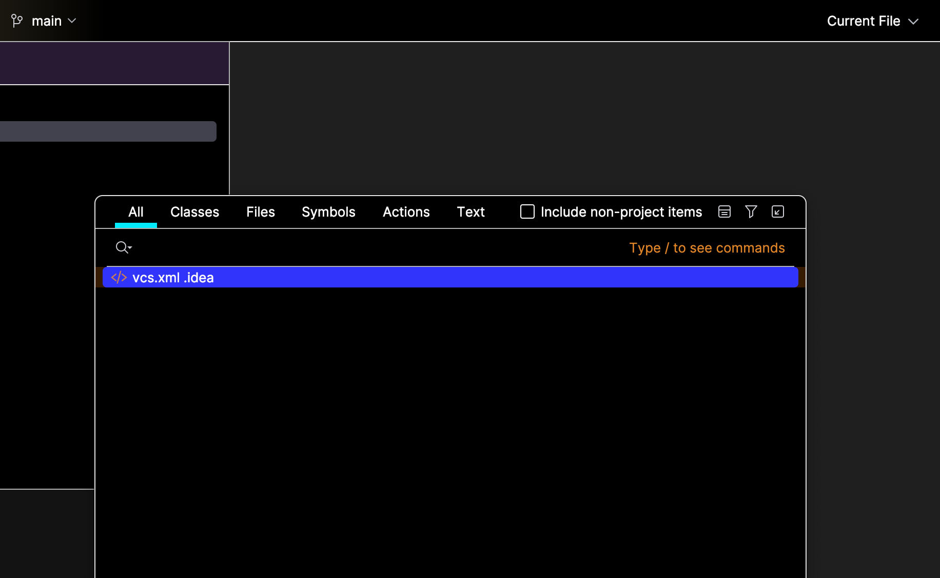
Fuzzy Find in IntelliJ enables you to quickly locate files, classes, or symbols. It guesses what you are looking for by keywords or parts of words to find what you are looking for. This can make coding faster because you don't have to spend time browsing files to find what you want.
You can use fuzzy find in IntelliJ by double-clicking the Shift key. When you do this, the following search bar will pop up, and you can just type a keyword or part of the item you are looking for, and IntelliJ will find it for you:
Gradle Stuff
You can access this Gradle tasks menu by hitting the (tootin') elephant on the top-right side of your screen:
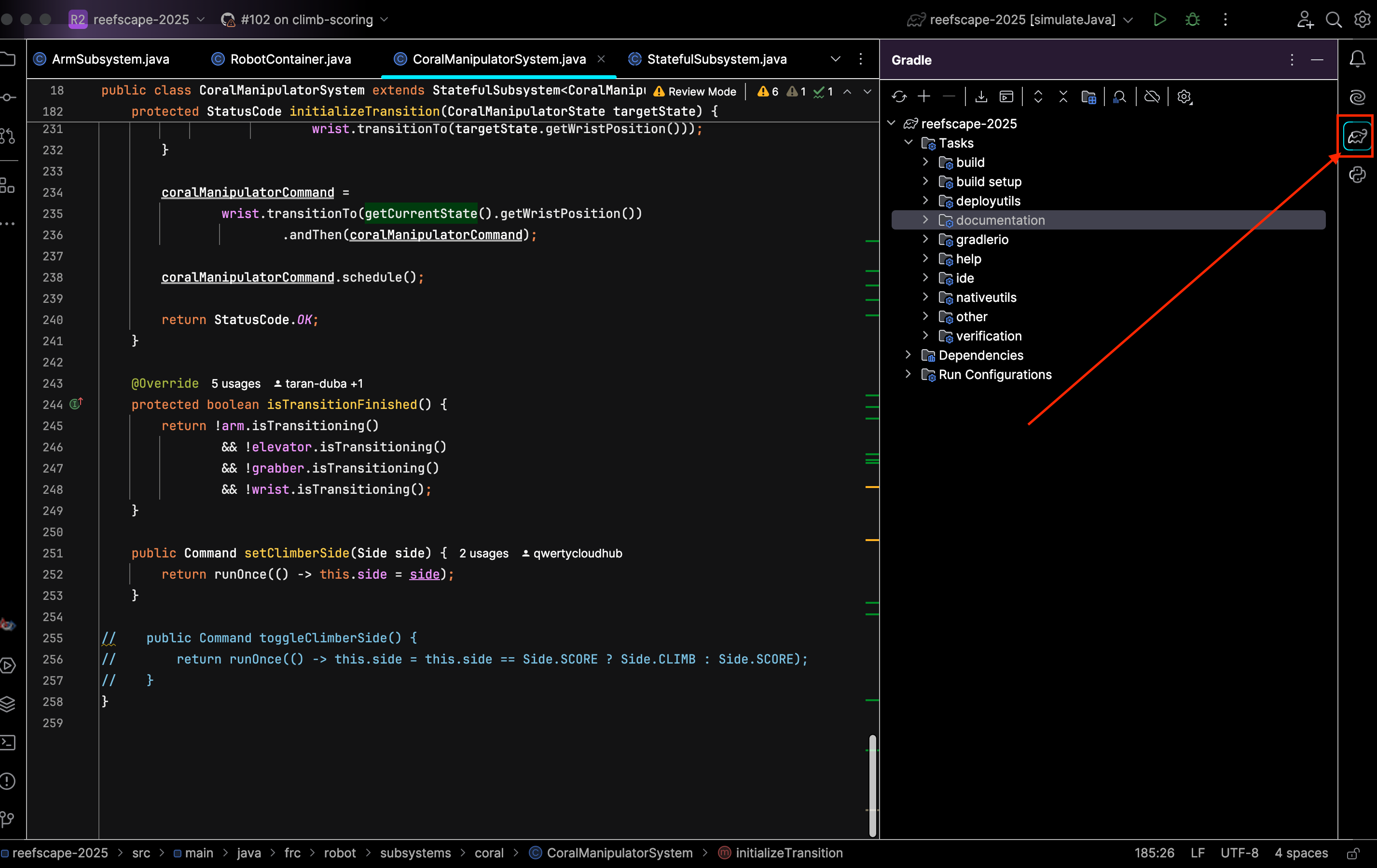
The ones you'll likely use the most are listed below:
- build: This is under the build dropdown in the menu. This compiles the code.
- deploy: This is under the deployutils dropdown in the menu. This deploys the code to the roboRIO.
- simulateJava: This is under the other dropdown in the menu. This will launch the simulation window and let you simulate your code.
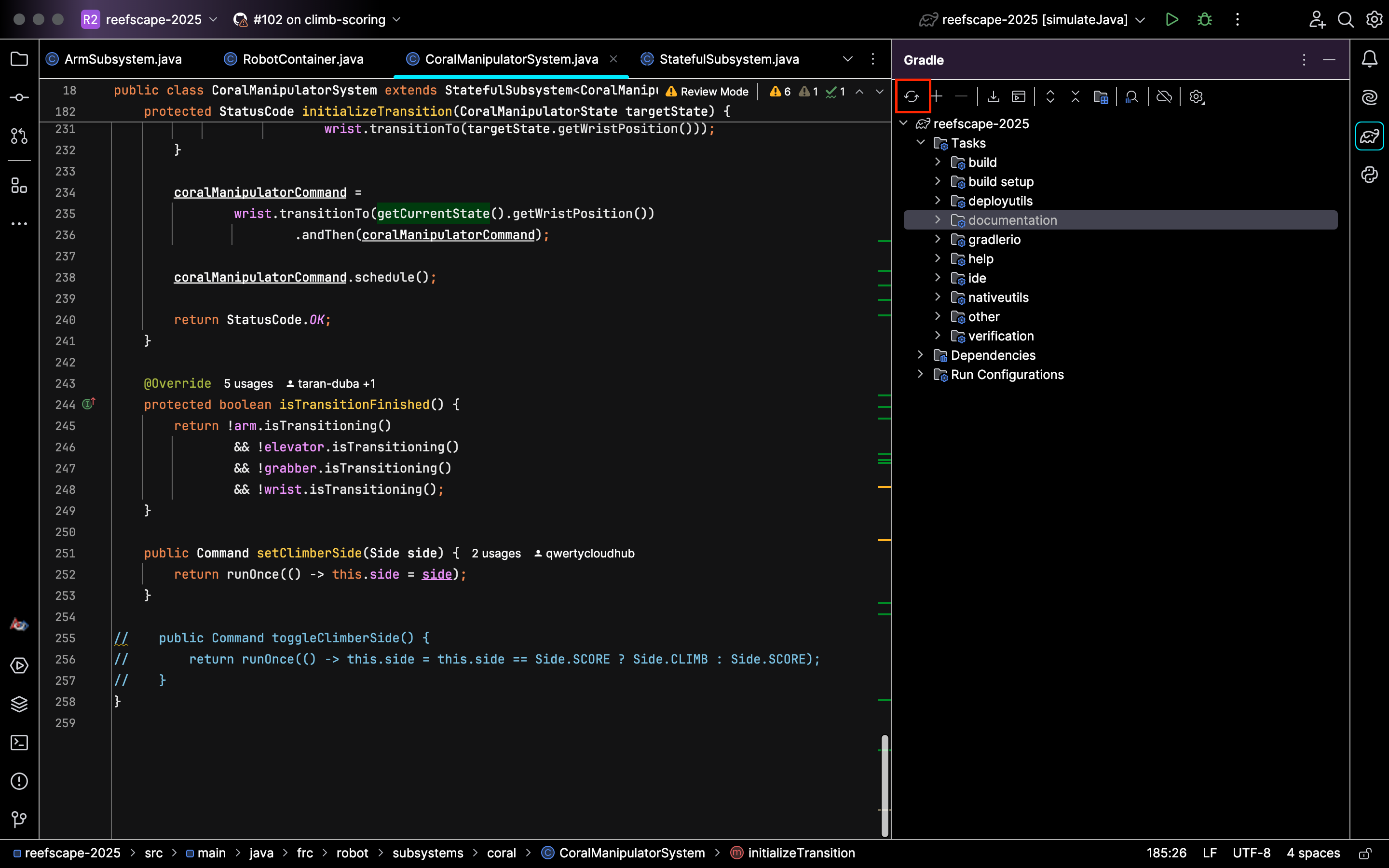
The Gradle refresh lets you refresh your project to sync up any changes to your Gradle config settings. In addition, it can also fix compilation errors. You can do this by hitting this button in the top-left corner of your Gradle menu:
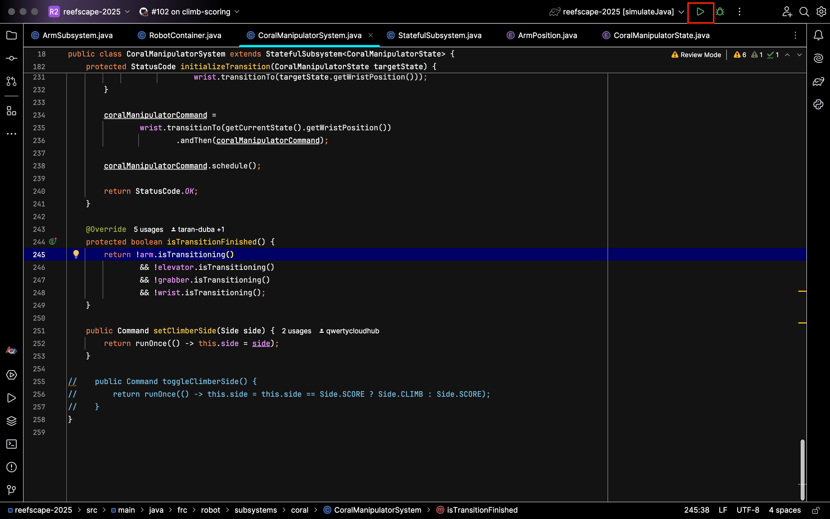
Note that after running a Gradle task, you can easily run it again by hitting this play button:
Invalidate Cache
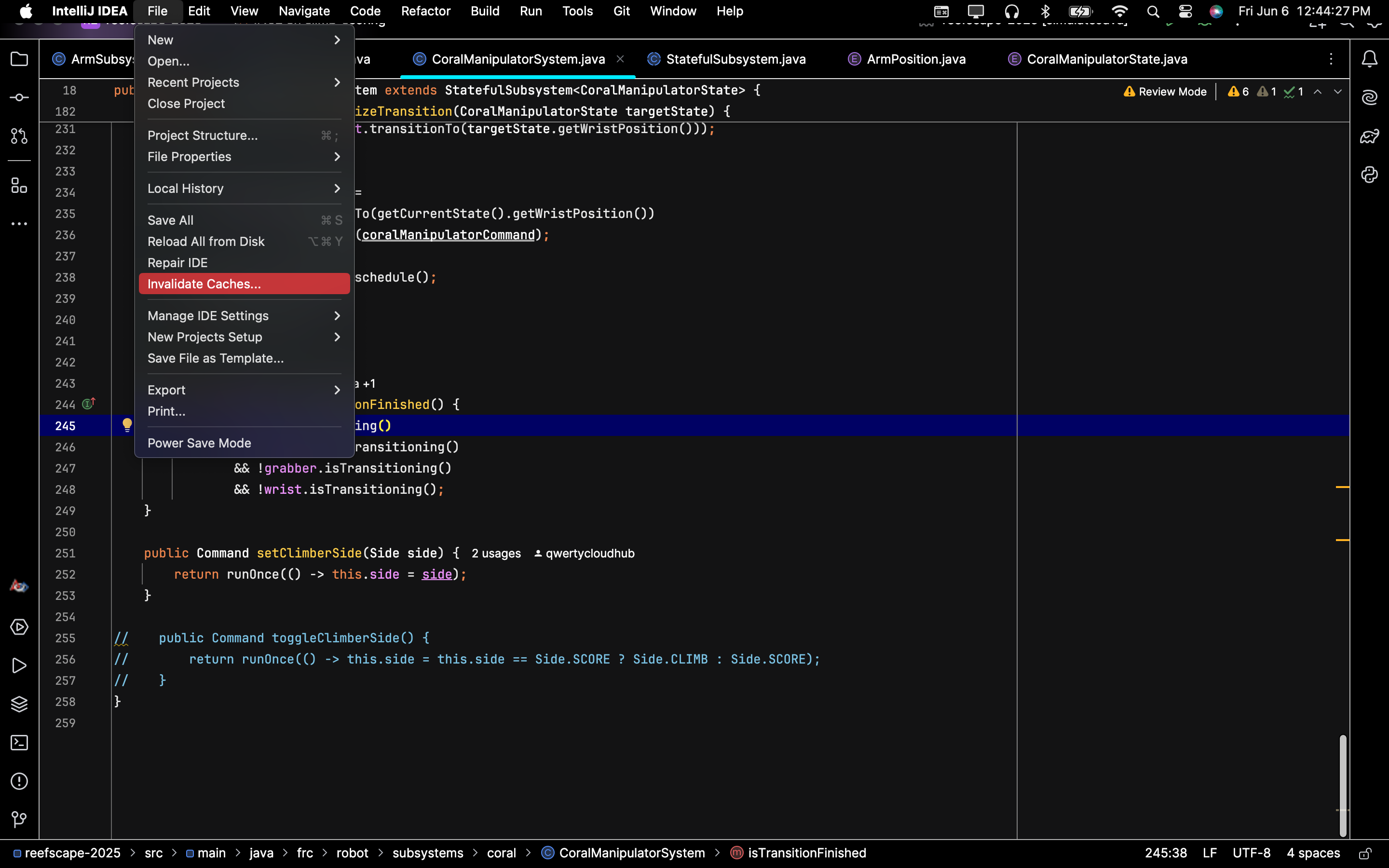
If you are having problems building, you may need to invalidate caches and restart the IDE to fix problems related to outdated or corrupted caches. You can do this by hitting File > Invalidate Caches as shown below:
Renaming Things
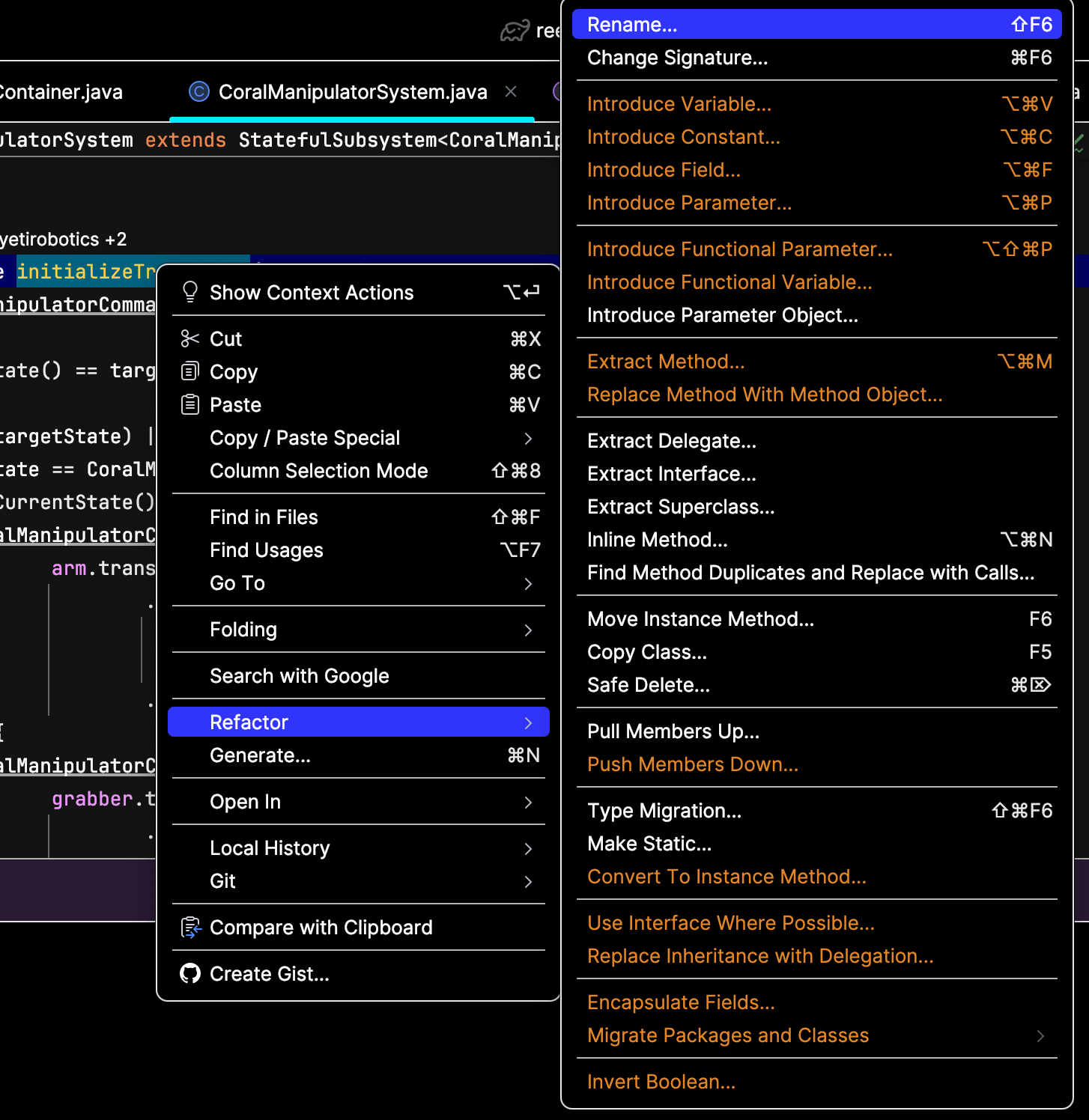
When you're renaming symbols, make sure you don't make the fatal (and suuuuuper goofy) mistake of only renaming one instance. This will lead to problems that can only be solved by throwing a magic ring into a volcano. Instead, right-click whatever you want to rename and hit Refactor > Rename, and type whatever you want the symbol to be renamed to. This will rename all instances of the symbol and ensure that you don't have to go on a whimsical adventure involving a cool archer elf. Below is the menu you will need to use:
Ctrl-Click
If you are using a Mac, replace Ctrl with Command
One of the most powerful tools IntelliJ will bestow upon you is the Ctrl-click. If you hold Ctrl while clicking on a piece of code, it will take you to its definition and show usages of it. Below is an example:
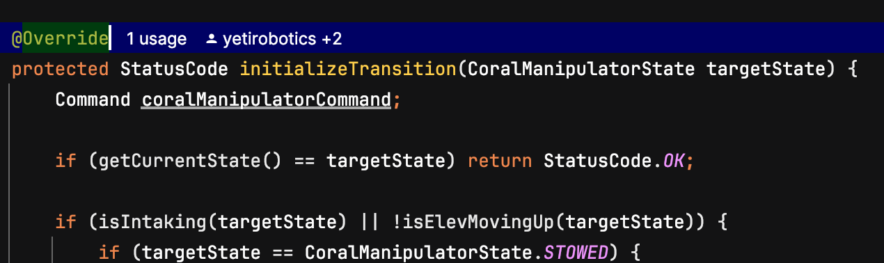 Before the ctrl-click
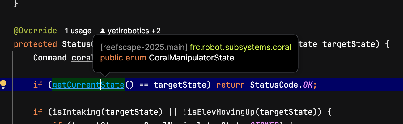 While holding Ctrl
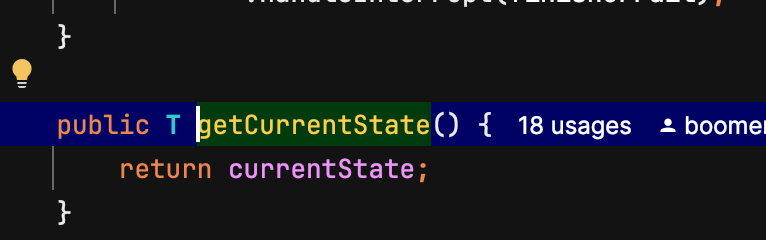 It takes you to the definition!
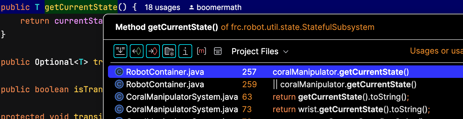 Ctrl-clicking the definition shows the usages!
Now you can Ctrl-click to your heart's content!
Git Actions
So you wanna work with other programmers on a project? On YETI, we use Git and GitHub for organizing contributions between programmers. You can access some Git actions from the IntelliJ icons, but some things are easier to do with the terminal. Note that you can access the terminal by hitting the button below:
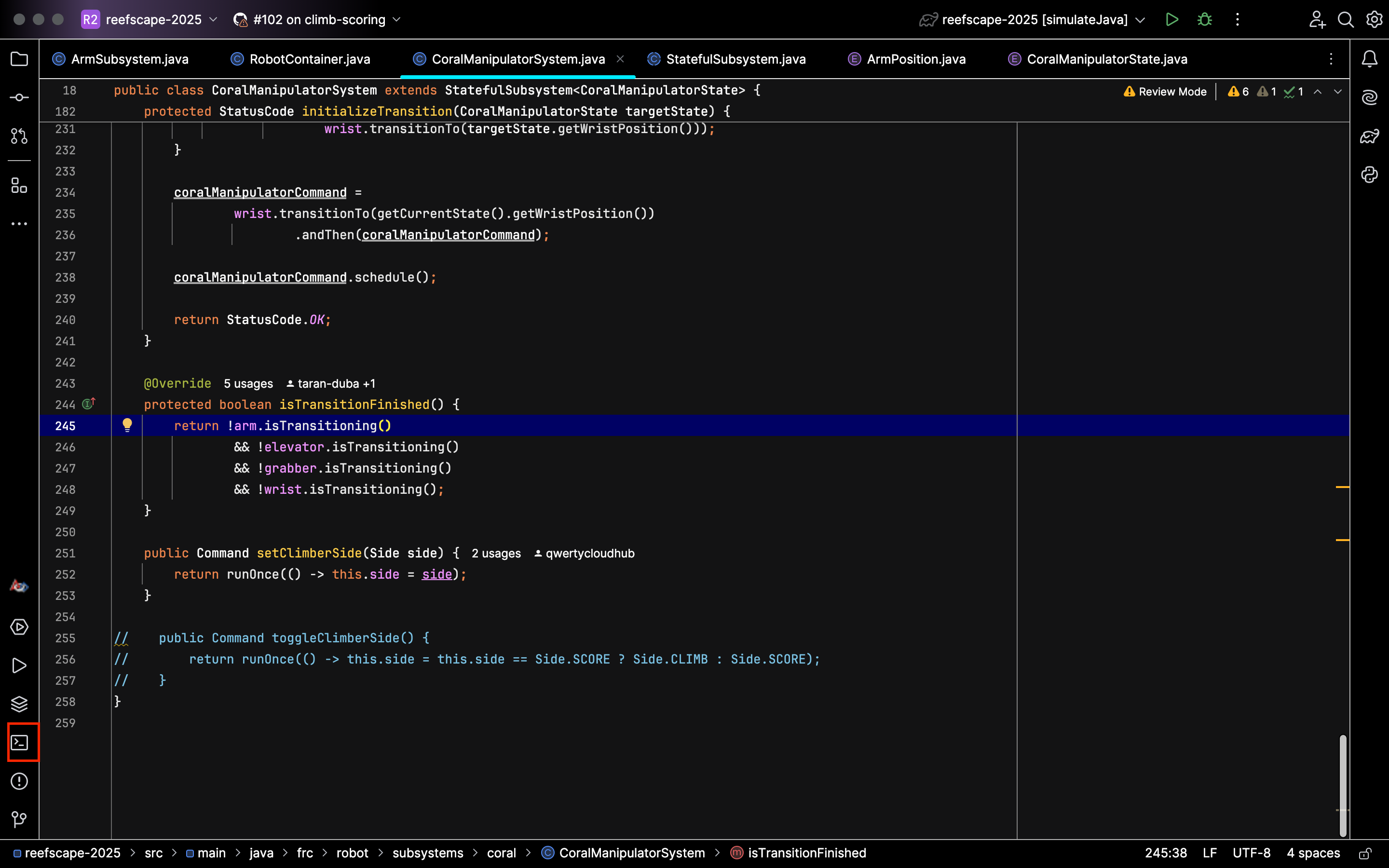
The following list outlines the Git actions that you'll likely use frequently.
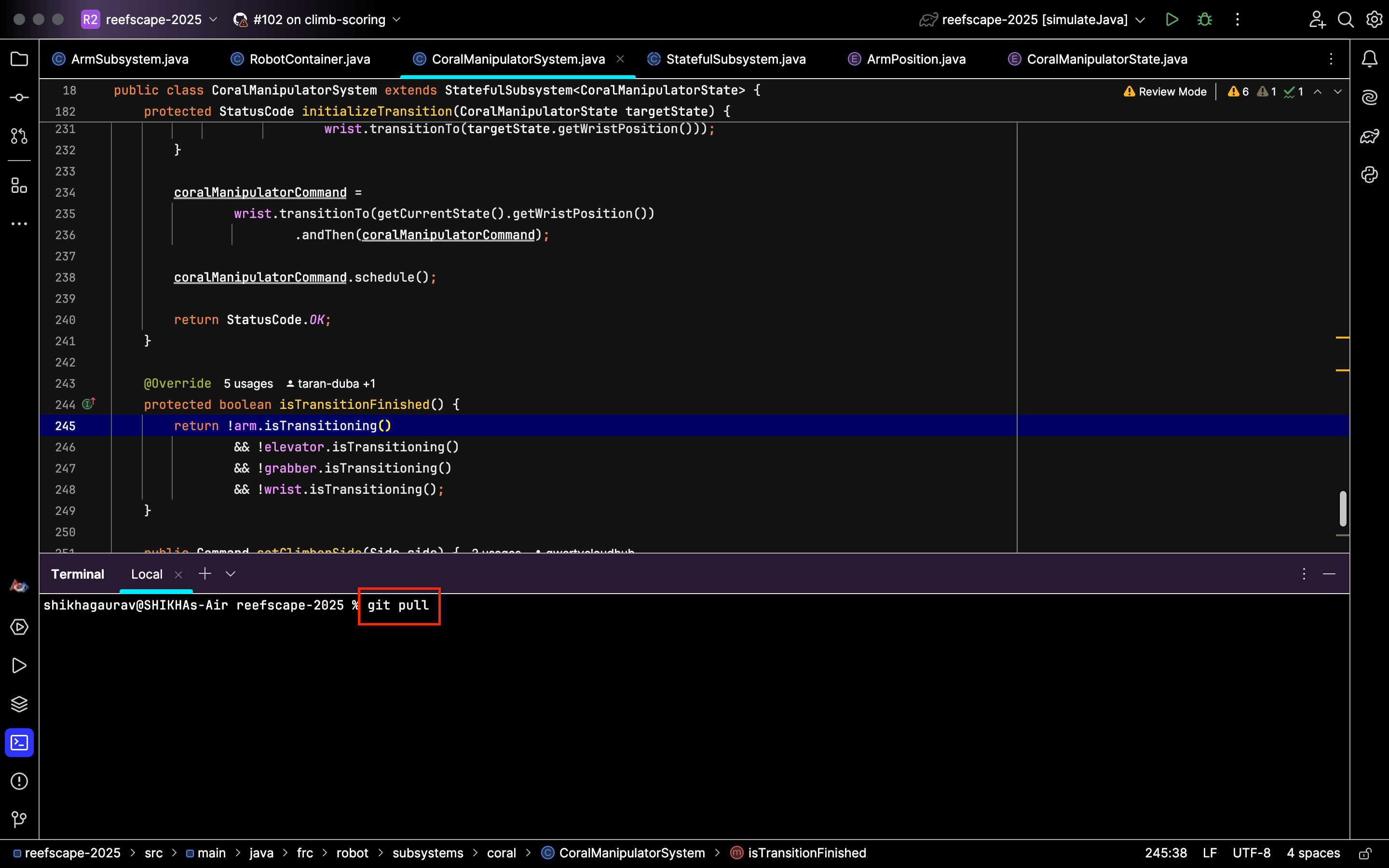
- Pulling: There are two ways to pull and update your project
- Use the terminal and type in git pull:
 Then hit enter, and your local branch will be updated.
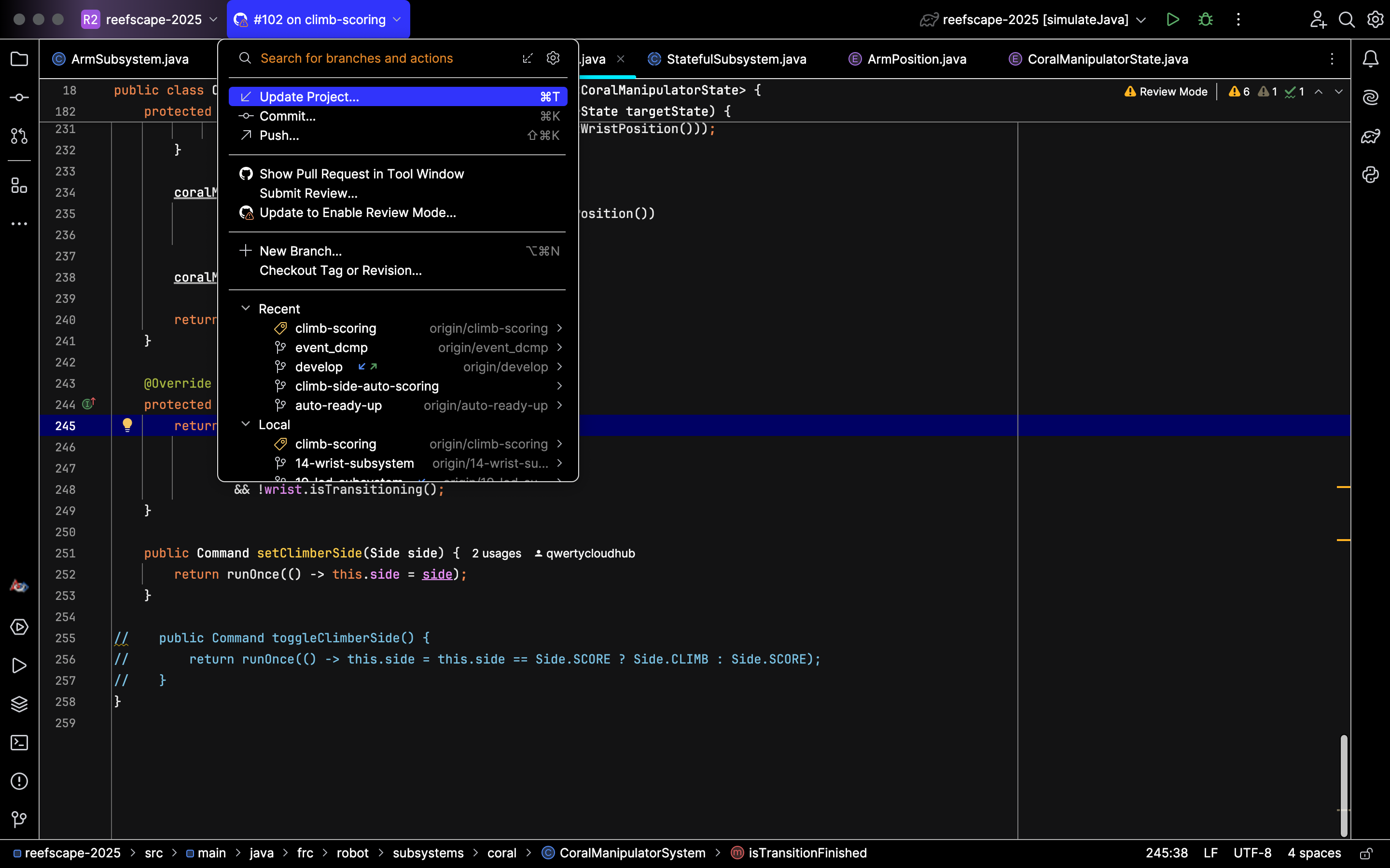
 - Select the branch name and then hit Update Project:

- Use the terminal and type in git pull:
- Committing: Committing is usually easier through the IntelliJ icons than through the terminal. Follow these steps:
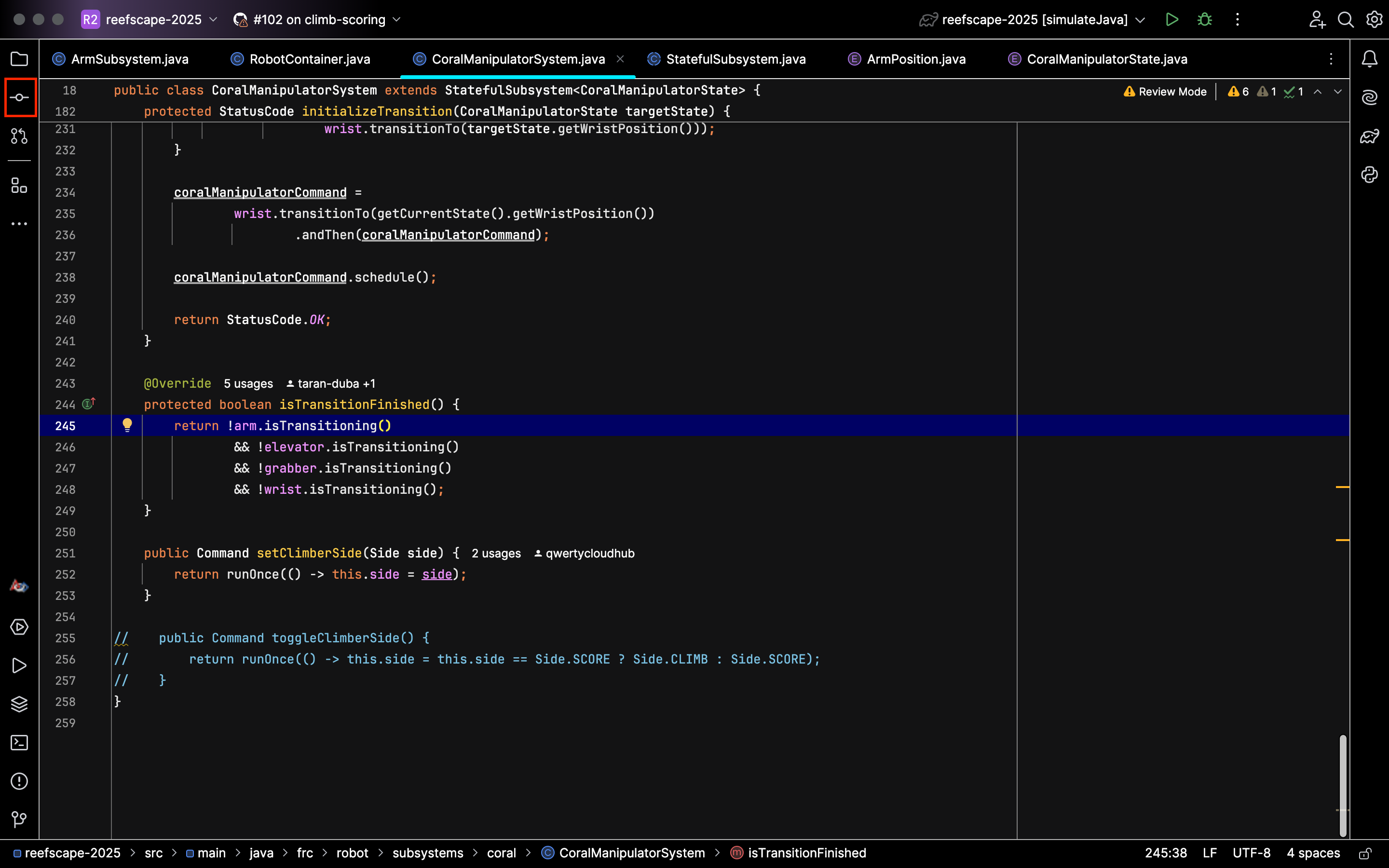
- Start by hitting this button:

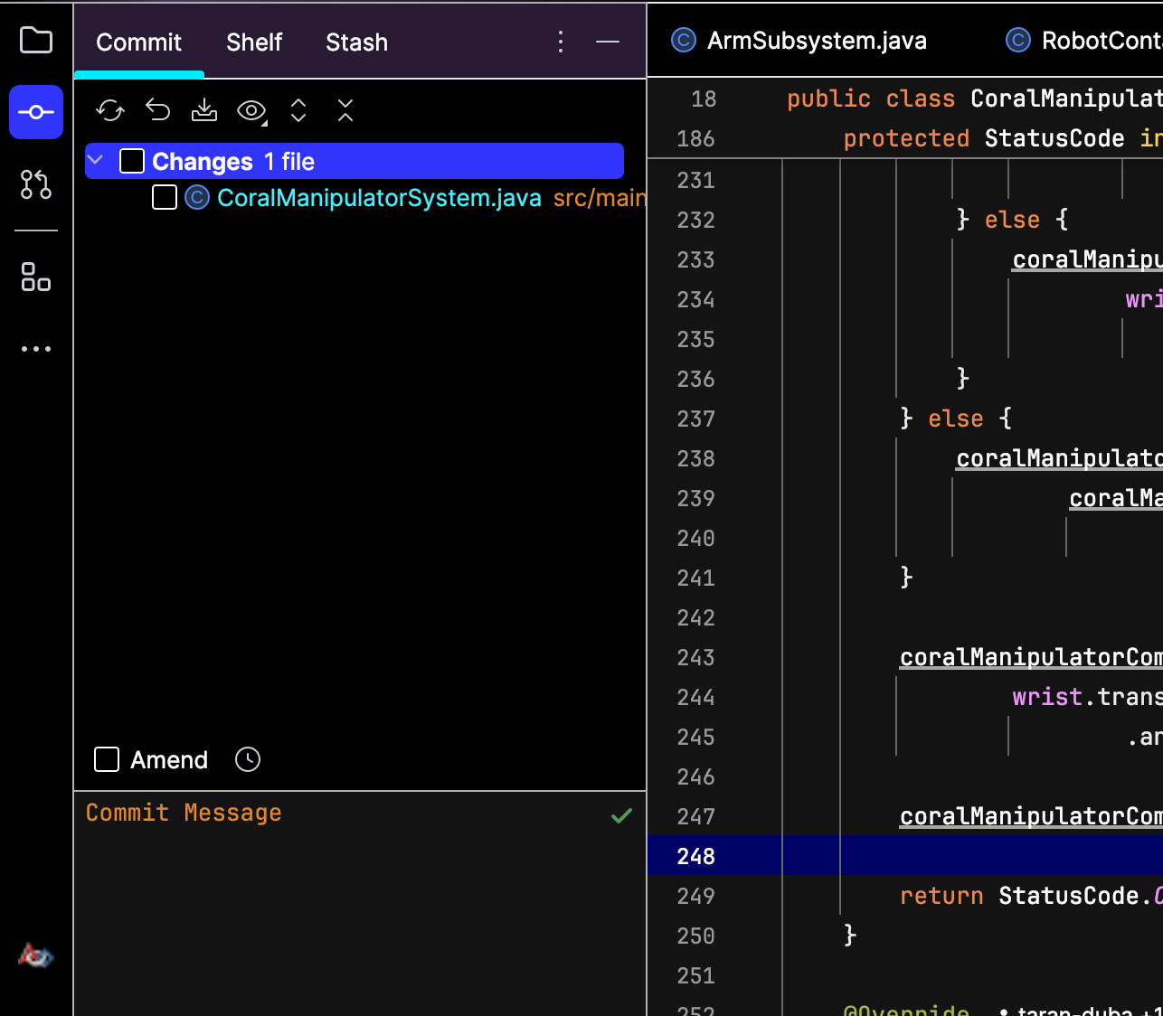
- The menu will show the files that you have made changes to:

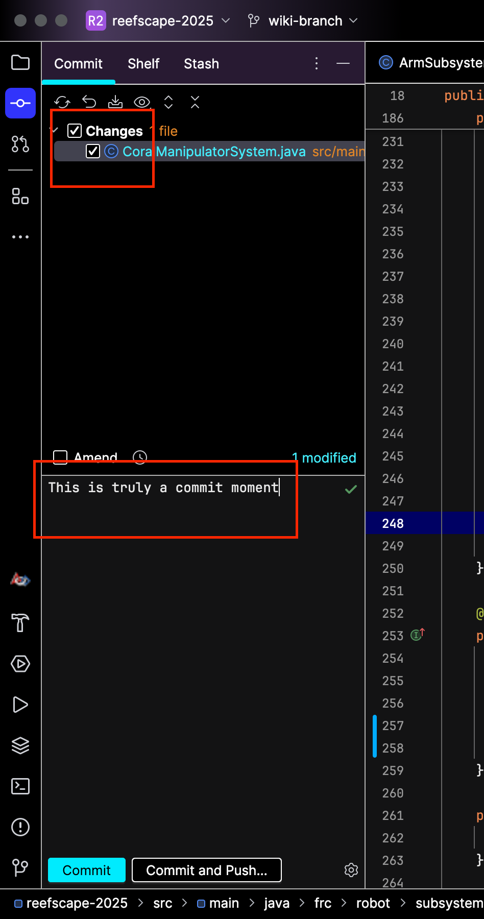
- Check the box to stage the changes and type out a commit message describing the changes you made:

- Then hit commit to save your changes locally, or hit commit and push to send your changes to the team repository. Your changes will show up in the repo: .


- Start by hitting this button:
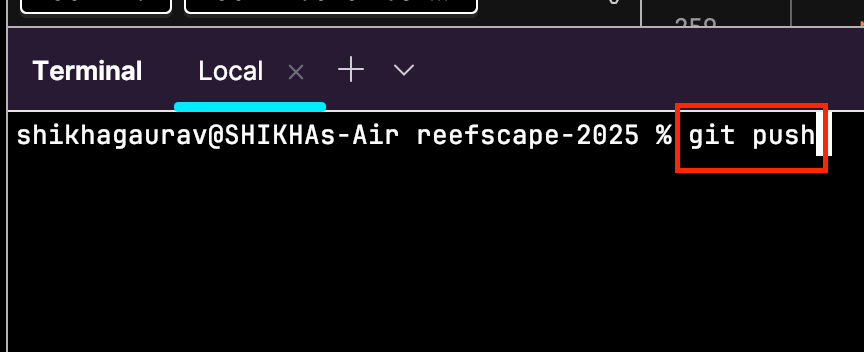
- Pushing: Simply type git push into the terminal and hit enter. The commits you have will be pushed to the repo:

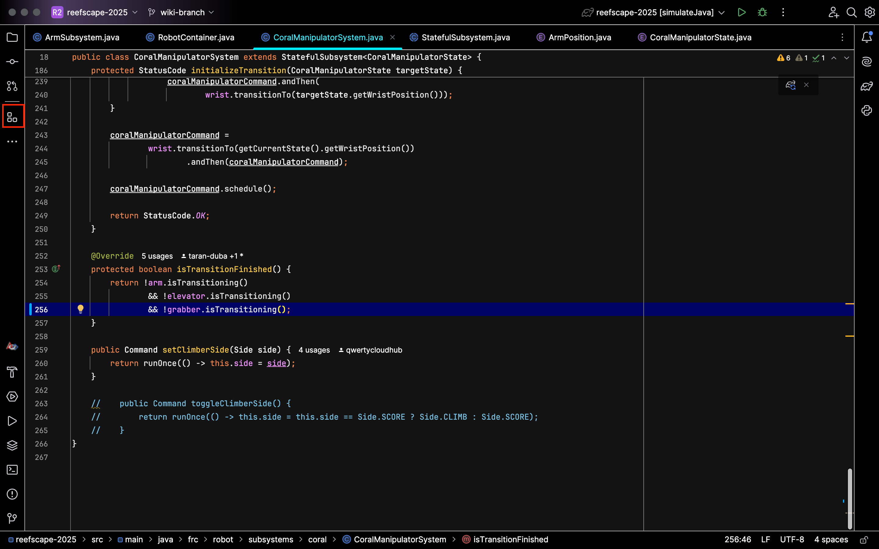
Navigating with the Structure Tab
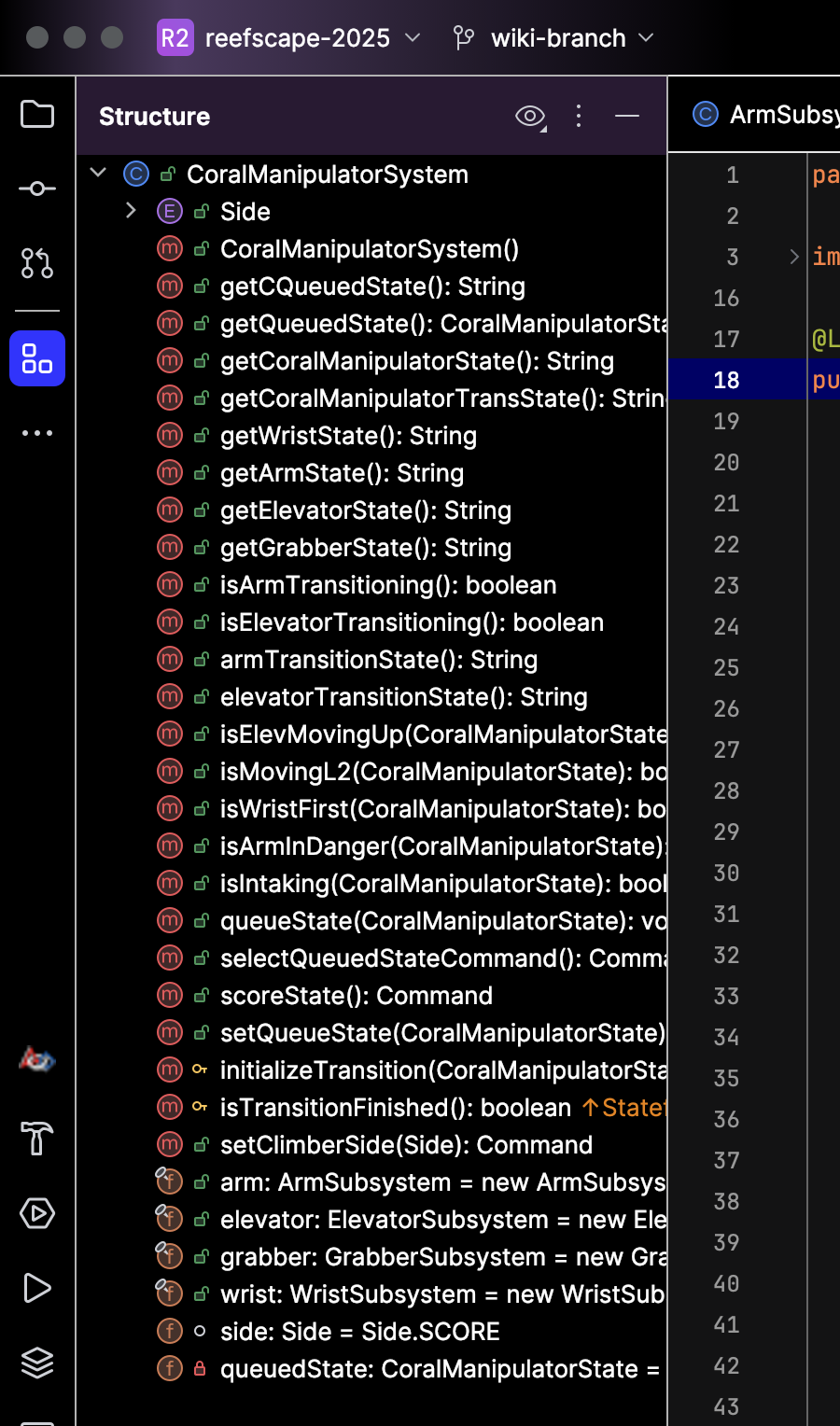
One of the best ways to navigate the structure of your project files is by using the Structure tab on the top-left side of your screen:
This will open the following menu and let you easily look through the structure of your file:
Getting started with a Romi
Romis are small robots that you program the same way you program the big robots we build for the season. they are a great way to get familiar with how commands and subsystems work. you can read more about romis here.
to get started programming a romi, make sure you have installed all the tools you need for robot development.
we have a starting template for programming the romi on our github here. to get started with it, follow these steps:
- click the use this template dropdown in the top right, then Create a new repository
- make sure your personal github account is selected as the owner
- give the repository a name. anything your heart desires
- click create repository
- you now have your own personal romi project
setting up on your computer
- you should now be on the page for your own romi repository. copy the url of this page
- open intellij
- open the file menu in the top left
- under the new dropdown, select Project from Version Control
- paste in the url of your repository
- choose where you want your project to be on your computer
- click clone
- in the new window, wait for the project to finish loading. the loading bar is in the bottom right
- test that your project is set up correctly by clicking the dropdown in the top right next to the green play button and selecting Build & Run Romi via Simulate Java
- click the green play button
- a new purple and black window should open up. if it doesn't or you see an error message, put a message in the #controls channel to ask for help
Configuring a Robot
Setting steer offsets for a Mk 4i drivetrain
- Put the robot up on blocks
- Begin with the bevel gear (the black ring on one side of the wheel) on the modules all facing inward
- Use a straight edge to ensure the modules on each side are all facing the same direction
- Deploy code that sets the angle offset to
Rotation2D.fromDegrees(0.0) - Open the driver station and pull up the labview (default) dashboard. go to the variables tab
- The value you are looking for could have any name. It will be derived from something like
Rotation2D.getDegrees() - Set this value to the angle offset for each module exactly
- e.g.
Rotation2D.fromDegrees(12.3243)
- e.g.
- Deploy code
- Test
- If a wheel is spinning the opposite direction of what it should be, add 180.0 to the angle offset
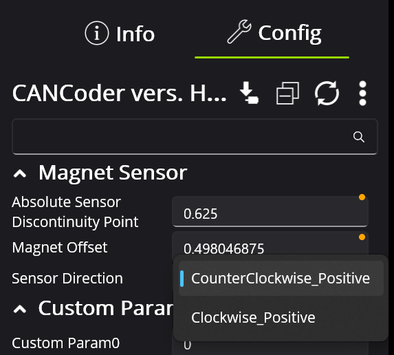
Setting the magnet offset for a CANcoder
- Move the encoder's mechanism to the desired home position
- Reset the magnet offset of the CANcoder to 0 in phoenix tuner
- Apply config (hit the button with the down arrow next to CANcoder Configs)
- Hit the green refresh button
- Check the absolute position of the CANcoder
- This will appear in a table under Self Test
- Set the magnet offset to the absolute position multiplied by -1
- Apply config
- Hit the green refresh button
- Confirm that the absolute position now reads 0
- If it is still significantly far off from 0, adjust the magnet offset number until the absolute position gets as close to 0 as possible. Remember to hit apply config and the green refresh button every time you change the magnet offset
- Set this new value in the code
- Deploy code
- Reboot the robot
- This is needed so the updated values in the CANcoder are properly distributed to the other CAN devices
- Confirm that the absolute position still reads 0 at the desired position
Flashing a Radio
Pre-2024 Champs Radios
Prerequisites
- Windows PC with WPILib Tools Installed
Steps
- Windows search for "Manage Network Adapter settings"
- Disable Wifi
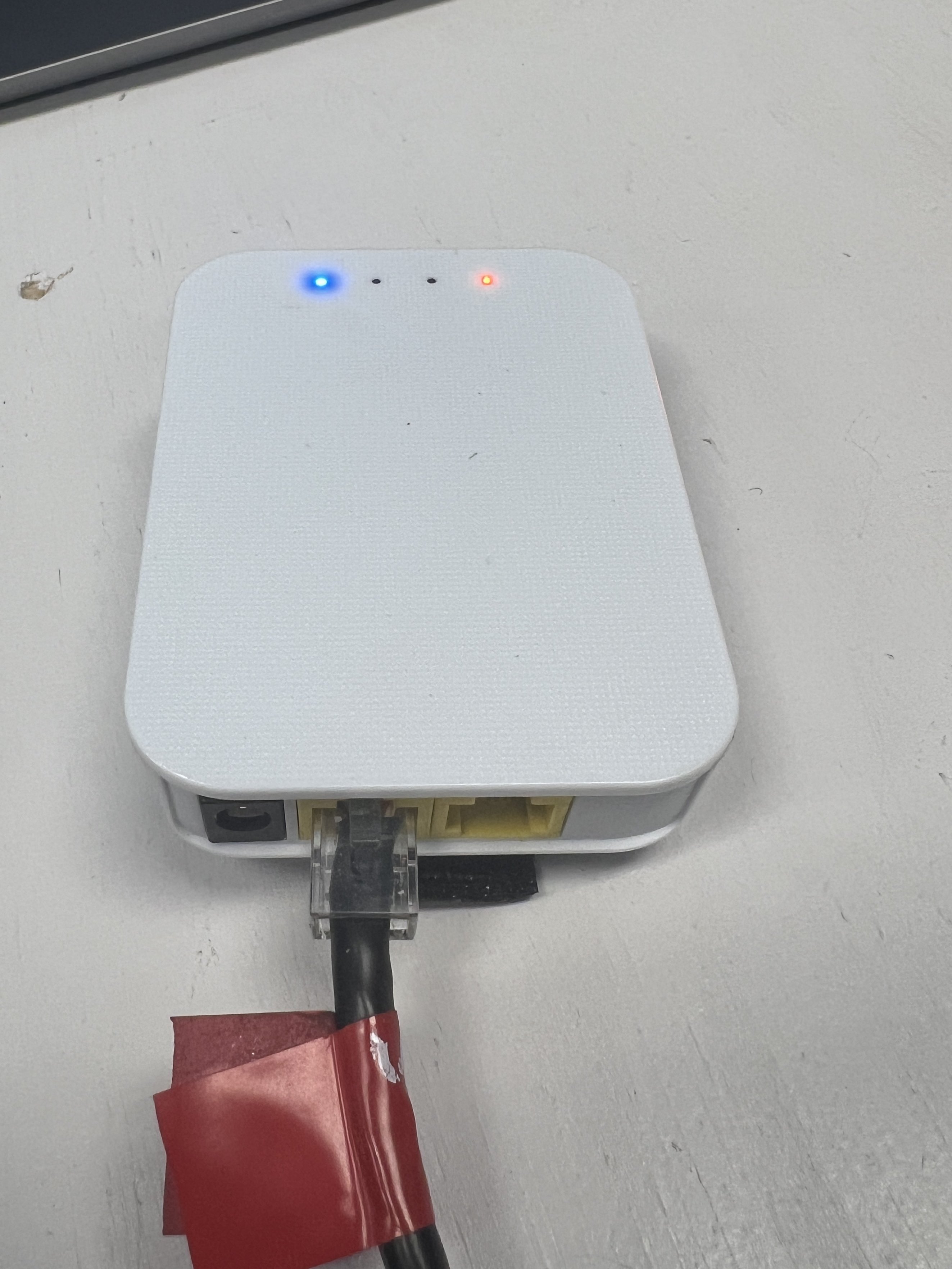
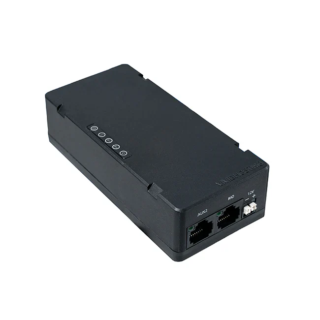
- Connect the Ethernet from the port closest to the power (18-24v POE, image included below) to the Radio Power Module (RPM). Connect the RoboRio side of the RPM to the computer.

- Open the Radio Configuration Utility application
- Set the team number to 3506 (or the number of the team you are configuring the radio for)
- Set the robot name. This is optional, but HIGHLY recommended. The name, if specified, will be put in the Wifi network name, and makes it easier to differentiate between robots.
- Go back to Network Adapter settings and re-enable Wifi
- Reboot the robot
If you encounter any issues, check out the "Programming your Radio" guide on WPILib (https://docs.wpilib.org/en/stable/docs/zero-to-robot/step-3/radio-programming.html)
VH-109 Radios
Prerequisites
- Windows PC with vh_network_assistant installed
- Ethernet Cables
Steps
- Plug one end of the Ethernet cable into the DS port on the radio while it's connected to the robot/Boardy and the other end into the Ethernet port/dongle (dongle recommended).
- In the Windows search, look up vh_network_assistant.exe (searching for it will make it pop up) and click "Run as administrator".
- Select Ethernet 1 if you plugged the ethernet wire into the computer's Ethernet port or select Ethernet 2 if you connected through a dongle.
- Hit Configure. This will configure the ethernet port to be able to connect to the radio.
- You should get a success dialog.
- After selecting OK in the success dialog, you will see a button for "Check Radio Status."
- Click that button. If you get the dialog mentioning the VH-109 or the other VividHosting radios, check to see if you plugged things in correctly and powered things up correctly. If it still doesn't work, then try steps 1-6 until it works.
- Once you get the success dialog with the radio specs, then select the OK button, and then select Yes to go to the radio configuration settings page.
- At the top of the page, you will be able to select between 2 different options of Robot Radio Mode and Access Point Mode. Make sure to select Robot Radio Mode.
- Set the team number to be 3506.
- Set the suffix to the robot name. If the robot name is undecided, ask a mentor before picking a suffix.
- Set both WPA keys to this -> YETI3506.
- Hit Configure and wait 5-10ish minutes.
- Go back and do steps 1-7 to get the dialog with the radio configuration. If it has changed to the correct suffix, team number, and versioning, you have succeeded! If not, then try again.
Help
If you feel stuck, ask for help, or visit the VividHosting docs.
Testing Robot Code
Testing code before merging it is important to ensure it works as intended. This page discusses how to checkout the correct branch, deploy the code, test it on the robot, and merge changes.
Checking out your branch:
Go to the terminal in Intellij by clicking on this icon in the lower-left corner of your screen:
![]()
When open, type "git fetch origin" to fetch to your local repository. Then, type "git checkout [branch name]" and insert the name of the branch that contains the code you want to test. It should look like this:

You should now be on the correct branch. To ensure all of your changes are on it, type "git pull" to update your branch. It should look like this:
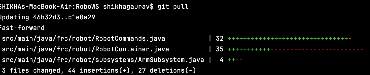
Congrats! You now have all the code that needs to be tested.
Deploying the code:
Now, you need to deploy the code to the robot. First, connect to the robot's WiFi. For our team, the network name will be in this format: 3506_robotName. Once connected, go back to IntelliJ and look for this in the top-right portion of your screen:
![]()
Ensure the dropdown is set to "Build and Deploy Robot." If that option is unavailable, you may have to scroll through the Gradle stting which you can find by clicking this icon:
![]()
You'll find the Build and Deploy Robot option in the Run Configurations folder:
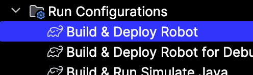
Once you've selected Build and Deploy Robot, hit the green play button. After about 30 seconds, the deployment will be complete.
Note that the Communications and Robot Code bars will turn red on the FRC Driver Station Application while deploying, but will return to green after deployment is complete. Also, if the Communications and Robot Code bars begin to cycle red and green, it means your code is crashing and there is an issue.
Hooray! The code is on the robot!
Test it out:
To run the code on the robot, go to the FRC Driver Station application. It should look something like this:
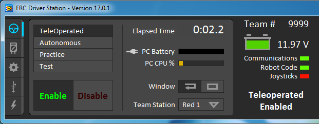
Ensure that the settings are correct. All three of the bars (Communications, Robot Code, and Joysticks) should be green. The battery should be sufficient. Ensure that you are on the correct drive setting (TeleOperated, Autonomous, Practice, and Test).
If it is in TeleOperated mode, you will need to manipulate the controller to test. If it is on Autonomous mode, ensure that the robot is placed correctly and the correct autonomous program is selected prior to enabling. Hit the green enable button to start the robot and test.
If it does not work as intended, then you will need to change some code and try again.
Nice! Your code has been tested and verified!
Merging changes:
Now that you've tested out your code and it works, you'll need to get it merged to make sure it's part of the offical robot code™.
Begin by commiting and pushing your changes. You can do this from the terminal, but it's easier to do through the IntelliJ menu bar. Click on this icon:
![]()
This will show you all of your changes. Type a commit message that details the changes made and their purpose. Make sure your changes are checkboxed. Then hit the commit and push button:

If a box pops up telling you that there are warnings, don't worry about it. However, if the box says that there are errors, then there are problems in your code that you need to fix (and maybe test) before pushing.
Your changes should now be pushed. Go to GitHub and open the repository. Then go to the Pull Requests tab:

Hit the New Pull Request Button in the top right:

This bar should pop up:
![]()
Keep the base branch development, but select the dropdown on the compare branch and change it to the branch with the the changes on it. Then hit the Create Pull Request Button and fill in the necessary information. Once completed, submit your pull request.
Once checks are completed, it may mention merge conflicts. GitHub provides ways to resolve these, so make sure those are fixed and any changes are pushed.
Once a mentor has reviewed it, they may request changes that you will need to go in and complete (and maybe retest). Once it is approved, it will be merged and will be part of the offical robot code™.
Yay! Good job testing!
Setting up Motors
Overview
There are a couple of steps involved with setting up your bot's motors, and this page will cover these steps.
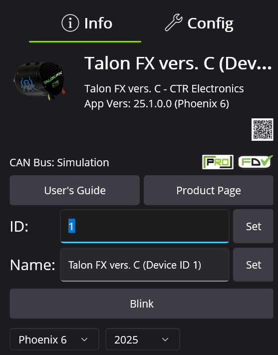
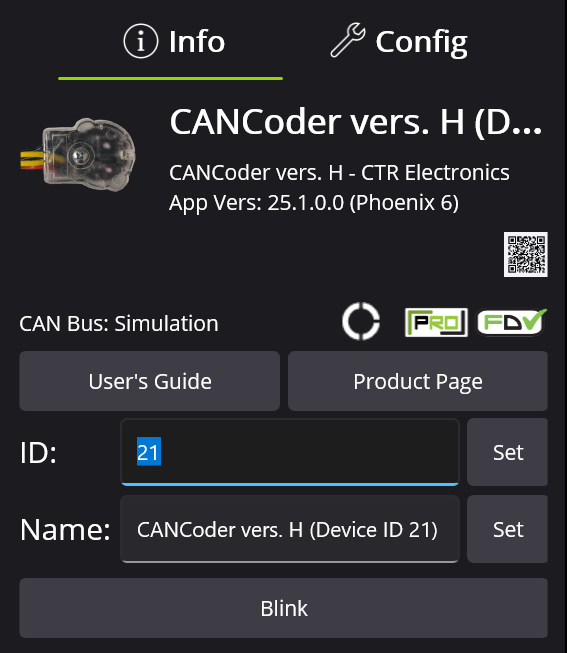
Updating ID and Name
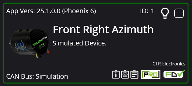
Updating the ID and name of motors contributes functionally to address the motors in code and organizationally to understand the purpose of each motor. You can update the ID number of the motor by typing text in the following box:
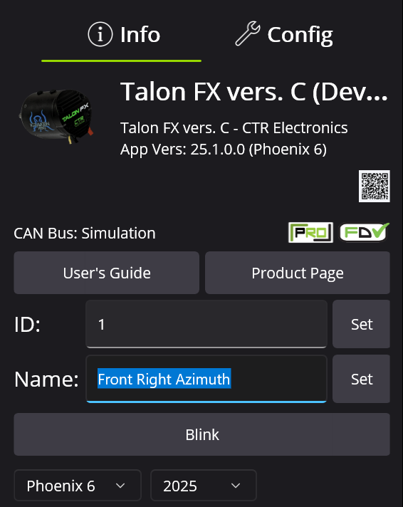
You can update the name of the motor by typing text in the following box:
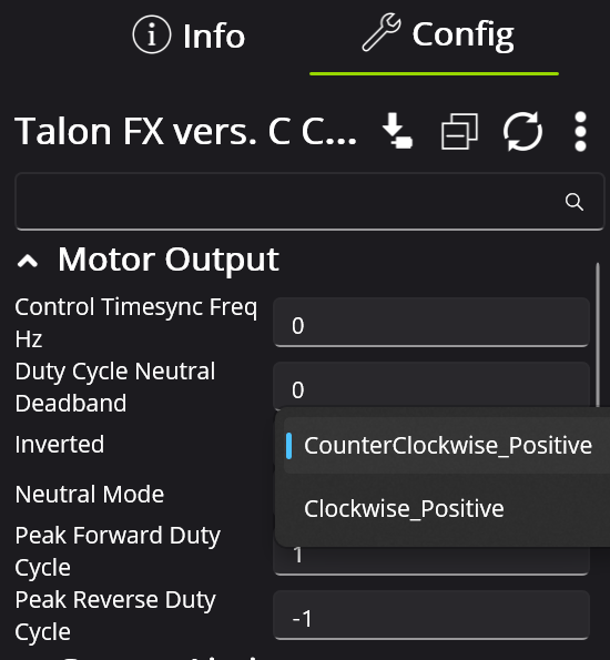
Motor Inversion
Sometimes, you need to switch the motor direction to ensure that the "forward" direction is positive. Also make sure that the Cancoder moves in the same positive direction as the motor it is assigned to. You can switch this in Phoenix Tuner as such:
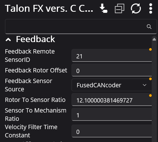
Cancoder Settings
Some motors require cancoders, which have IDs of their own. You can update the cancoder ID by navigating to the cancoder itself and changing the ID number here:
Then change the motor configs to ensure it is assigned to the correct cancoder:
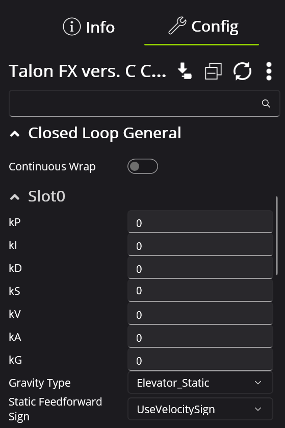
Tuning Configs
The tuning configs are located here:
Drivetrain Motors
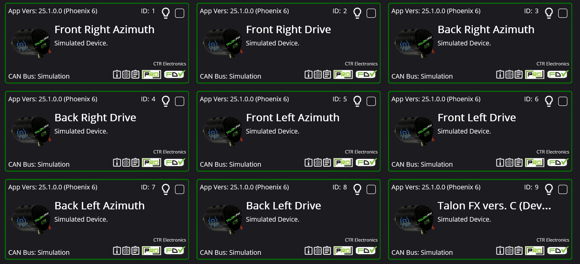
For the sake of organization and easy access, we ID our drivetrain motors sequentially from 1-8. This is because Phoenix Tuner displays devices in order of ID, and therefore keeps the drivetrain motors at the top of the page:
Update Configs in Code
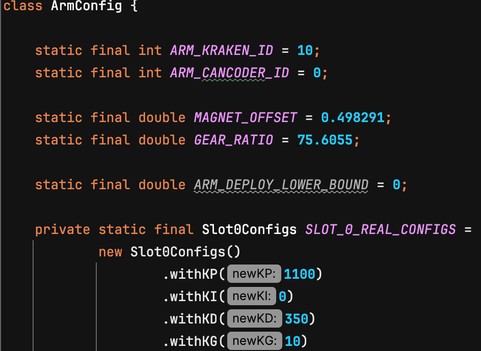
Changing the configs in Phoenix Tuner is important to make sure they are correct, but after this, you need to update the configs in the code. Configurations in Phoenix Tuner reset to what is in code on power cycle, so it is important to keep the configs in code up to date. For example, if the motor I am trying to update is the Arm motor, navigate to the following config file:

Then find the settings you want to update and change them:
Update Firmware
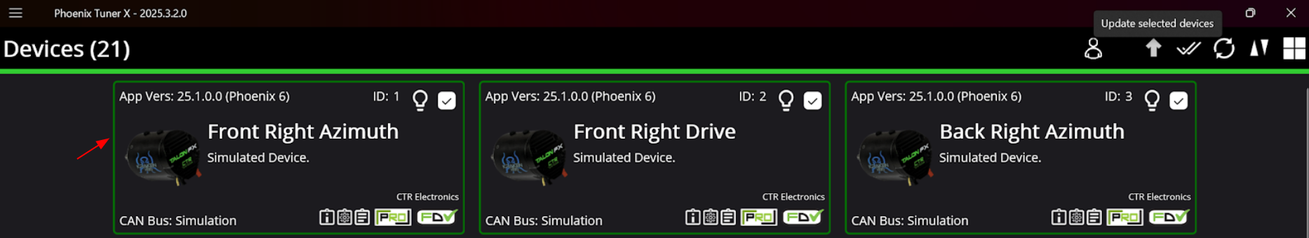
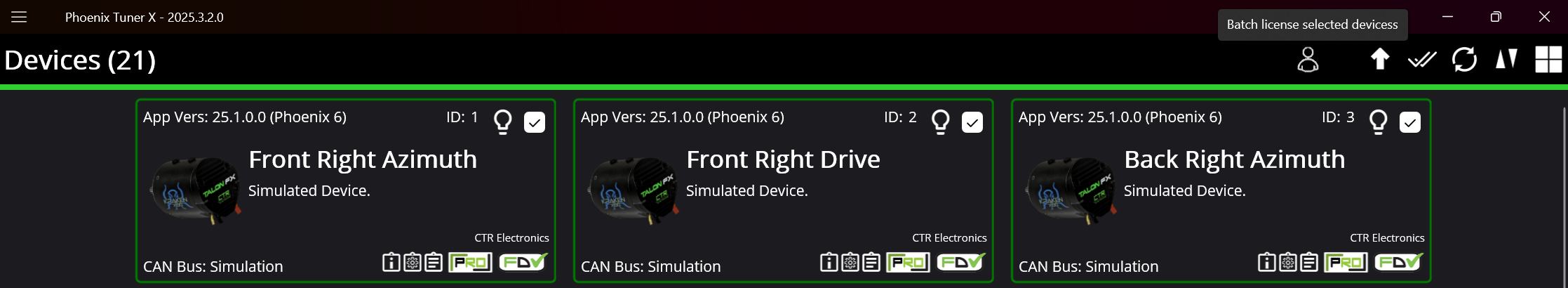
Make sure your motors are using the latest firmware version, usually the border around each device as pointed by the red arrow would be yellow if the firmware needed updating. To update, click the little checkbox in the corner and the upward facing arrow that appears in the top right of your screen.
Licensing Motors
For much of the tuning YETI does, the motors must be Phoenix Pro Licensed indicated by the little PRO icon in the corner.
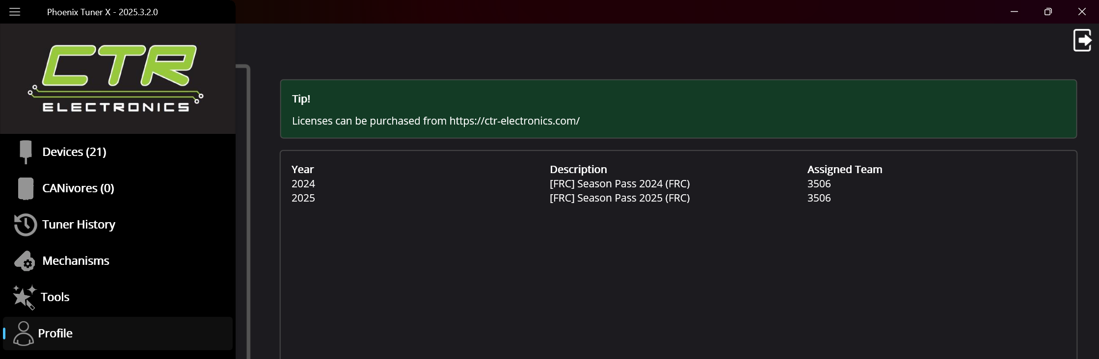
To license a motor, first unsure you are logged in to your CTRE account by checking under Profile on the side panel. The login details in the pinned messages of our Controls channel in Discord. Once logged in you will see what licenses are available to our team. There are only a certain number of license seats per year/season, but it is well over enough for the number of motors we use.
The actual process for licensing is kind of convoluted. You have to be connected to the robot to access the motors and select them, and click the person looking icon in the corner.
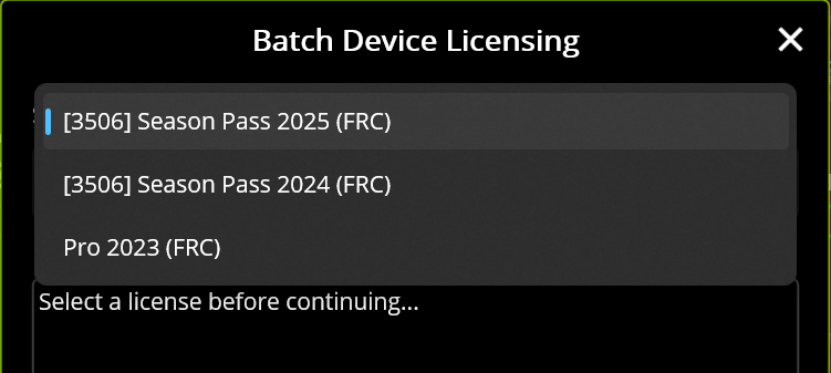
That'll bring up this box where you select the current year's pass.
Then it displays the motors you have selected, make sure these are the right ones and connect to the Internet before you continue.
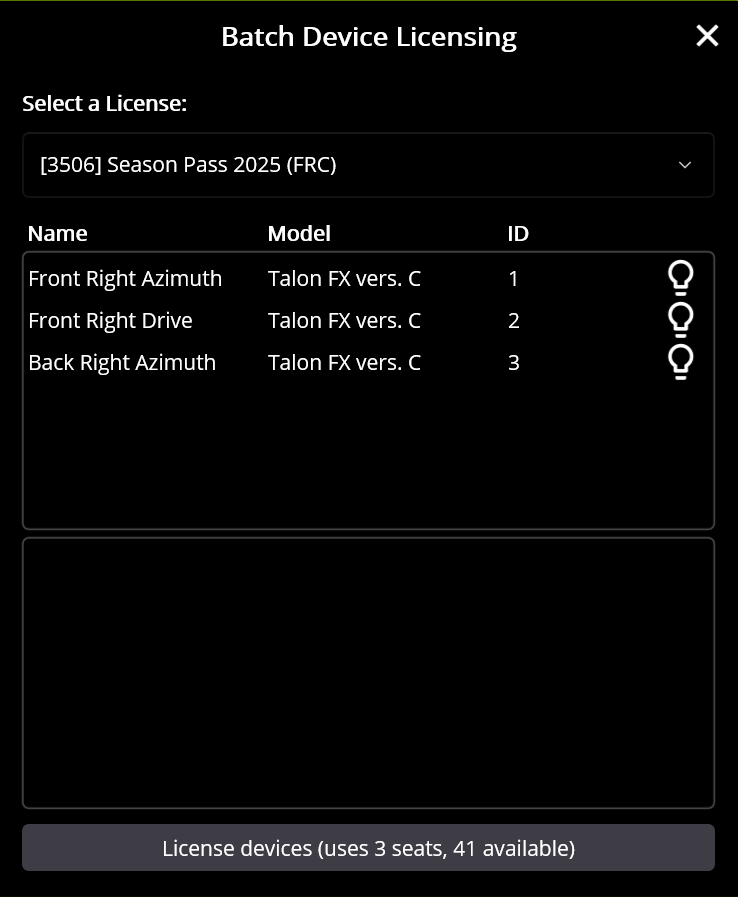
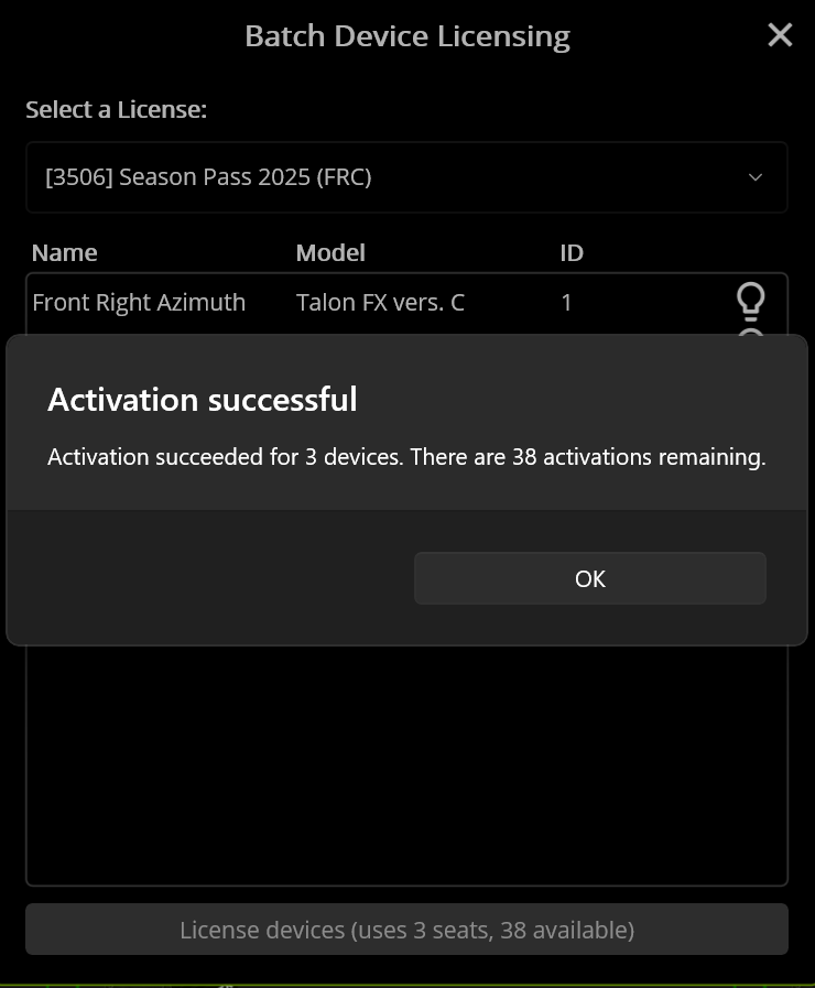
Once you are sure, allow the pop-up to strike fear into your heart
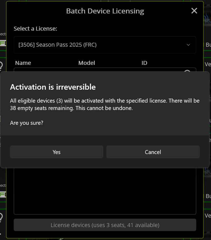
Success!
Re-zero code for drivetrains
This is just a random article that's meant to help you out with zeroing your drivetrain.
If you are using the CommandSwerveDrivetrain from your CTRE Tuner Constants, you have it easy!
All you have to do is use drivetrain::seedFieldCentric for your code!
However, if you're using the AdvantageKit drivetrain setup, you have it slightly different.
We re-zero the drivetrain by using the poseEstimator in the AKit setup.
The appropriate code for this is: poseEstimator.resetRotation(0). However, the number you pass in matters here. If you're on the Red alliance side, you would pass in 180. If you're on the Blue alliance side, you would pass in 0.
Hopefully this clears things up for you. If not, ask in #programming in the discord server and we'll be happy to help you out!
Setting up a new robot (Roborio)
Rio and Radio setup
- Flash rio
- If it's a rio 2, use balena etcher
- If it's a rio 1, use the roborio imaging tool
- Set the roborio's team number
- Although there is a roborio team number setter tool, it sucks and sometimes doesn't work. Use the roborio imaging tool to set the team number regardless of it's a rio 1 or 2
- Flash radio
- Connect to the radio over ethernet
- Go to http://radio.local
- Set the team number
- Set the robot name
- Set the password to YETI3506
- Hit apply
- Power cycle
- Deploy code
CTRE Setup
- Connect to robot
- Verify CAN busses are all good
- All devices should be flashing orange
- Make sure all IDs are unique
- Devices of different types can have the same ID. Devices of the same type cannot have the same ID
- e.g. A Kraken X60 and a Pigeon can both have ID 1, but there can only be one Kraken X60 with the ID of 1
- Devices of different types can have the same ID. Devices of the same type cannot have the same ID
- Update CTRE firmware
- License motors
- Name motors
- Set IDs
- Sync with code
- Confirm motor directions
- Sync motor directions with CANcoders
- Zero CANcoders
- Save CANcoder offsets in code
- Deploy code
- Power cycle
Gitting Good at Git
This chapter will go over two main things:
- What are Git and Github? What are they useful for and how are they used in the real world?
- How do we use Git on YETI?
Git Slideshow
This is the presentation that YETI gives as part of our software curriculum on using git. Take a look!
Tools of the Trade
This chapter will go over some of the tooling we use to make our code functional, efficient, automated, and easy to debug.
Table of Contents for Software Tools
Table of Contents with links for all the software tools we use to code robots here at Yeti!
Git - A version control system widely used in the industry and on our team that helps track code changes, manage branches, and collaboration with the team.
Github - Online platform for hosting Git repositories, allows for code sharing, pull requests, and team collaboration. This is where we have all of our code stored, viewable publicly.
WPILib - The official library used by us and all other FRC Teams to code robot subsystems, motors, sensors, and much more. Should answer a good amount of questions you have, or at least lead you to somewhere where you can find an answer!
Phoenix 6 - CTRE’s Motor Controller Library that allows us to configure and support devices such as TalonFX. Also really helpful and can answer a lot of the questions you have regarding Motor Control.
Phoenix Tuner - CTRE’s application that allows you to configure, test, and update CTRE CAN devices like Talons. Helpful documentation regarding tuning as well.
PhotonVision - An open-source vision system that detects AprilTags and other such objects and sends pose data to the robot. Helpful documentation regarding vision related questions.
Limelight - Another vision system that detects AprilTags and other such objects, similar to PhotonVision. Helpful documentation regarding vision related questions.
AdvantageKit - A logging framework that records all robot data and actions. We plan to experiment with this as a team this season, so it has very helpful documentation!
AdvantageScope - A visual dashboard that reads logs from AdvantageKit and displays field position, sensor data, and timelines in real time or replay. This is also something we use a lot as a team!
Localization - The process used to calculate the robot's position on the field using data from encoders and vision inputs like AprilTags.
Driverstation - FIRST’s official software that we use to control the robot during matches, viewing system status, and switching between robot modes.
Simulation - A WPILib feature that allows teams to test robot code on a virtual field without needing a real robot.
Path Planner - A path generation tool that lets teams design and follow autonomous paths, especially for swerve and tank drivetrains. We use this as a team to generate autonomous paths!
Choreo - Another path generation tool that lets team design and follow autonomous paths. We are looking into Choreo this off-season, and comparing it with Path Planner to see which one is better for our team to use!
Elastic and Elastic Documentation - A customizable FRC dashboard that connects to NetworkTables for live monitoring and debugging. This is the type of FRC Dashboard we use at YETI!
Network Tables - A public-subscribe messaging system that is used to communicate/send data between the robot, driver station, and other such things.
Current Solution for PhotonVision 2027
With SystemCore still being in development, PhotonVision does not have an official release for the vendordeps.
Tunes for the Road
Tuning is one of the most important aspects of programming. It ensures that your mechanisms move smoothly and quickly. It is important to understand how to tune PID control loops by using Pheonix Tuner.
Plotting and Scheming
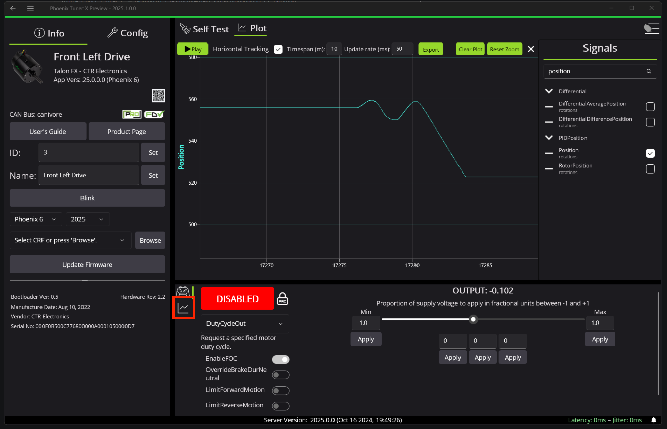
Plot (pluh):
One of the most valuable tools for your tuning endeavors is the Phoenix Tuner plot. The reason this is so useful is that it shows you how much your mechanism is off (in terms of position and velocity) in an intuitive manner.
Read through this guide to understand plotting with Phoenix Tuner:
https://v6.docs.ctr-electronics.com/en/stable/docs/tuner/plotting.html
Signals to Plot (pluh):
-
Position: The actual position of the motor according to the motor (or the CANcoder if there is one)
-
PIDPosition/Reference: The expected position of the motor; The position that you want the motor to be at
-
Velocity: The actual velocity of the motor
-
PIDPosition/Reference Slope: The expected velocity of the motor; The velocity that you want the motor to be at
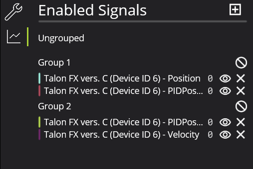
Plotting Tips:
-
Axis Alignment: One of the most annoying things to deal with when plotting is when the axes for multiple signals are misaligned. To fix this issue, you can group certain signals together. Generally, I put Position and Reference Position in one group and Velocity and Reference Velocity in another.
-
-
In the Phoenix Tuner window, go to the following tab.
-

-
Then, hit the + button to add a new group and drag the signals you want to the correct group.
-
-
-
Presets: It's a good idea to use the three preset boxes to quickly set the target position for the motor at your whim.
Key Terms with Tuning
Error
- The difference between 2 lines (i.e. Position & Reference or Velocity & ReferenceSlope)
Gain
- Tuned values such as kP, kS, or kV
Binary Search
- The process of finding an accurate gain while tuning
- Start at 1 and keep on doubling until it is too much (e.g. 1 ➔ 2 ➔ 4 ➔ 8 ➔ 16)
- Once it is too high, take the average of the current number, and the previous number (16 is too high, so the avg of 16 & 8 is 12, so try that)
- Then, you have to make a choice for what to do next:
- If this new number (12) is still too much, take the avg of the current number and the previous number which was still under the target (the avg of 12 and 8 is 10, so try that)
- If this new number (12) is too low now, take the avg of the current number and the next higher number which was over the target (the avg of 12 and 16 is 14, so try that)
- Repeat this decision over and over until you find the number that is a good match for the target
Closed-Loop Control
- Uses tuned gains to go to a set position or reach a certain velocity
- Usually relies on a sensor, such as the inbuilt encoder on the TalonFX or an external CANcoder to minimize error
- Consistent and accurate results
- Used for arms, flywheels, or pivot
- Examples: MotionMagicTorqueCurrentFOC, Position Voltage, VelocityTorqueCurrentFOC
Open-Loop Control
- Just spins a motor using just power
- Relies on timeouts or conditions, not sensors
- Used for intake or indexer
- Examples: DutyCycleOut, VoltageOut
kP
- The larger the difference between the current and target positions, the more power it puts to the motor to reduce the error
- Typically will cause some oscillation
kI
- If there is a consistent error between 2 lines, this gain will gradually reduce the difference between them
kD
- Resists change in movement of the motor
- This gain helps to dampen the effects of kP, reducing egregious amounts of oscillation
kS
- The 'S' stands for Static Friction
- The amount of extra force needed when the motor starts moving to combat the Static Friction
kV
kA
- This gain increases the acceleration of the motor
- This makes something like the Position line steeper the more it's increased
kG
- This is the amount of extra force the motor needs to combat the force of gravity
- This is especially important in an elevator to make sure it keeps its vertical position
Tuning a CANrange
A tuned CANrange is especially important to make sure detection is accurate and reliable!
Read through this guide for some more in depth examples and instructions:
https://v6.docs.ctr-electronics.com/en/latest/docs/application-notes/tuning-canrange.html
CANrange Overview
CANranges output many signals to plot in Phoenix Tuner/AScope, however Distance, SignalStrength, and IsDetected are the 3 most important ones:
- Distance is a measure (in meters) of how far an object is from the sensor
- SignalStrength is how accurate the CANrange thinks the distance is
- IsDetected is a true/false boolean (1 for true & 0 for false) of whether the CANrange detects something → dependent on the tuning you will do below
Make sure to add these 3 signals to the plot while tuning!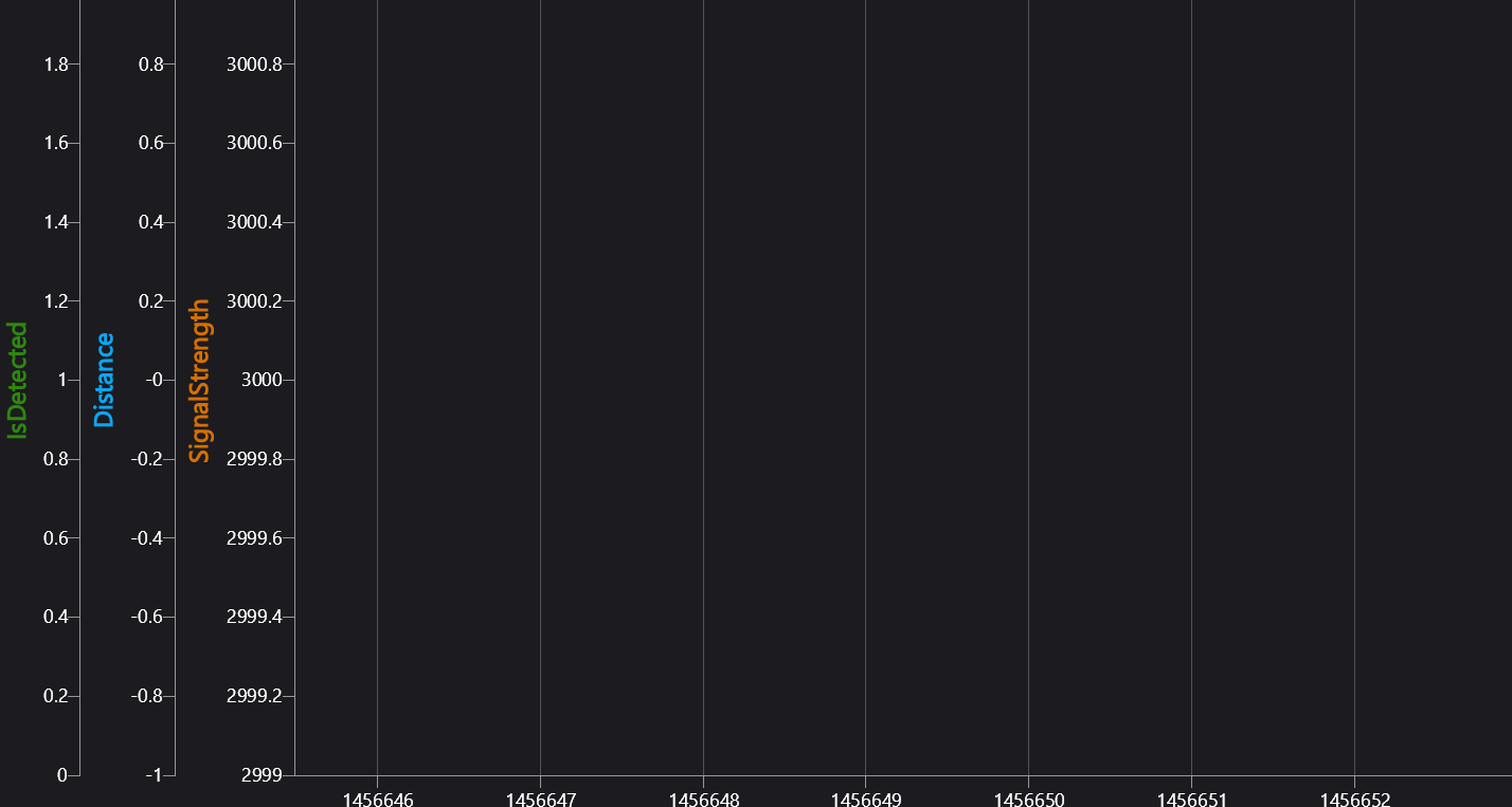
Tuning in Phoenix Tuner
Go to the Config section of the CANrange → the values under the FOV Params & Proximity Params headers are the main values you will be tuning for accurate readings.
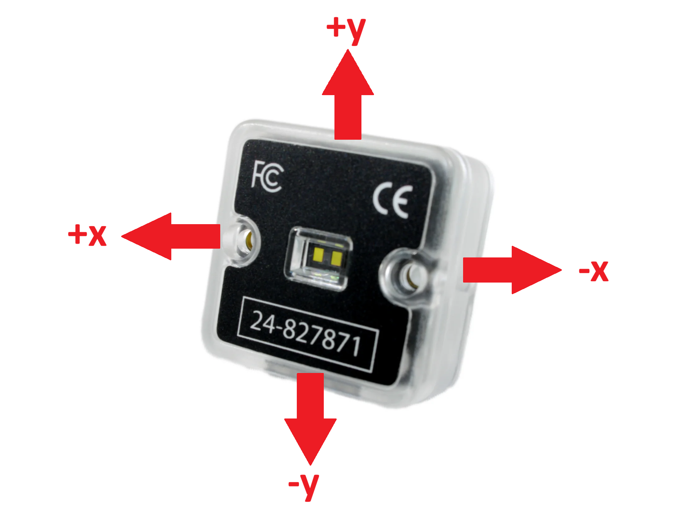
FOV CenterX / CenterY
These values (in degrees of rotation) are used to tell the CANrange where the center is and where it should be looking for objects.
-
-11° to 11°
FOV RangeX / RangeY
These values (also in degrees of rotation) are used to tell the CANrange how far away it should look from the center for objects
- 7° to 27°
|
Use this handy dandy image to check which directions are x, y, positive, and negative:
(The actual sensor part facing towards you) |
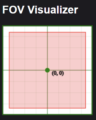
There is also an FOV Visualizer in Self Test that helps you see more clearly where the CANrange is looking: |
Min Signal Strength For Valid
This is set to 2500 as a default, and this a pretty good starting value. Check your plot for SignalStrength to see if you should adjust this value to be higher or lower.
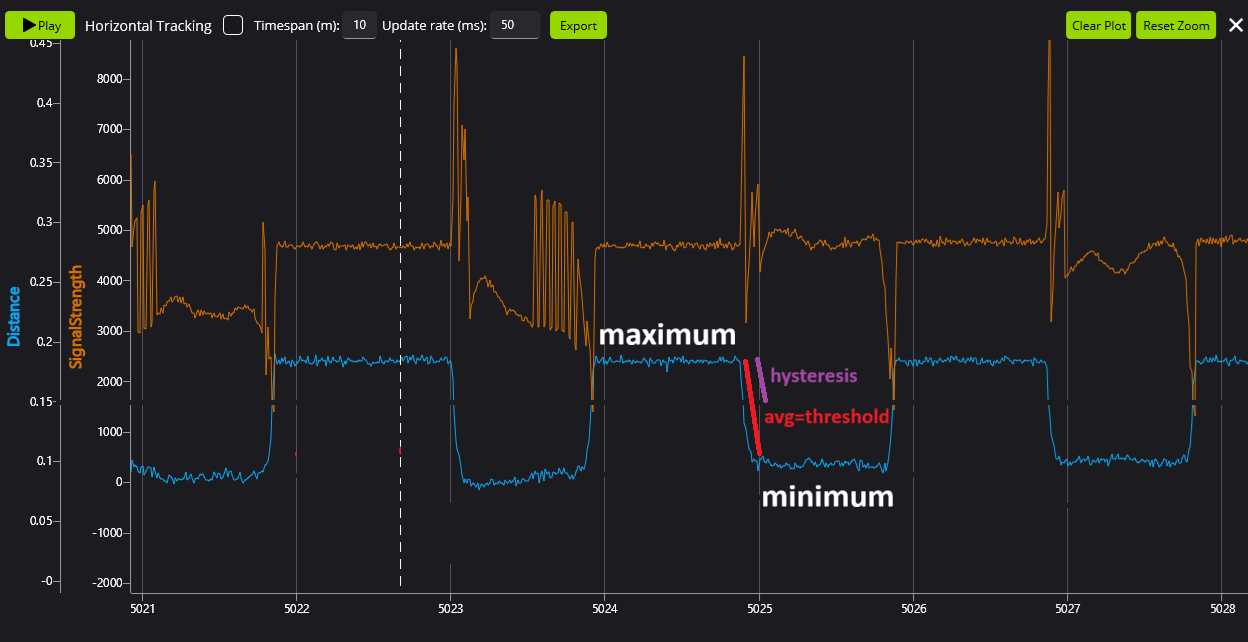
Proximity Threshold
This is the most important value to tune! If the distance is less than this value, then the object is detected. Make sure you are plotting Distance on the graph, and then:
- Place an object in front of the CANrange and see the distance decrease on the plot → this is the minimum distance
- Remove the object from the CANrange and see the distance increase on the plot → this is the maximum distance
- Average the values of minimum and maximum distances together, and this is your new Proximity Threshold (in meters)
Proximity Hysteresis
This value (in meters) tells the CANrange the extra distance less from the Proximity Threshold before it recognizes the object as detected and the extra distance more before the object is no longer detected.
For example if the Proximity Threshold was 1.0m and the Proximity Hysteresis was 0.1m then
- When the distance is ≤ 0.9m, the object is detected
- When the distance is ≥ 1.1m, the object isn't detected anymore
Proximity Hysteresis is especially useful when the CANrange is detecting in a noisy environment, and it allows the distance to change quickly without it thinking it's no longer detected.
The Hysteresis should generally be a little bit less than the difference between your Threshold and your maximum/minimum
Your CANrange is now tuned! It's always a good idea to fiddle around with the values a little bit to get your desired output, but this is a great starting place!
Position Tuning with MotionMagicTorqueCurrentFOC
This is a simple guide on how to tune MotionMagicTorqueCurrentFOC
You can find the official Phoenix Tuning Guide here.
Firstly, and most importantly, find your maximum and minimum setpoints!!!!!
Put these as preset position rotations in Phoenix Tuner.
If you don't, your robot will break!
Signals:
Add the following signals to the plot:
- Position
- PID Position (Reference)
- Velocity
- PID Velocity (Reference Slope)
Create two groups to create uniform scales (feel free to change colors as necessary to increase visibility):
- Position & Position (Reference)
- Velocity & Velocity (Reference Slope)
Tuning:
Make sure your motors are working together:
To do this, move each motor in the mechanism separately with positive DutyCycleOut to find inversions.
Simulation:
In sim, we don't need to worry about kG and kS because gravity and static friction don't affect simulation tuning. Then, follow these general steps:
- Binary Search kA to get the slope of your Position line to match the Reference line
- Add kV to maintain the Position line after its peak to keep on matching the Reference
- Try and use kA and kV as much as you can to match the line and limit the amount of PID tuning
- Binary Search kP to reduce the error between the Position and Reference (try not to make it oscillate to much: you should only need a little)
- Lastly, add some kD to dampen out the oscillation made from kP
- You can tweak these gains to minimize the error between the Position and Reference
You can keep on doubling the Motion Magic Acceleration and Velocity to make the mechanism move faster as well
Real Life Tuning:
- Zero all PID gains.
- Increase kG to find the smallest possible kG that stops the arm from moving.
- Increase kG and find the largest possible kG that stops the arm from moving.
- Set kG to the middle of the two values.
- Set kS to half the difference between the two values.
- Set a setpoint relatively small (typically 0.1 mechanism rotations).
- Follow the steps above from the Simulation Tuning
- Increase kP until you notice significant overshoot.
Velocity Tuning with MotionMagicVelocityTorqueCurrentFOC
How to tune for Velocity
We like to use MotionMagic because it makes speed changes smoother! We use MotionMagic for basically all of our motion profiles.
When using a velocity profile, you are trying to get the motor to spin at a specific velocity instead of a rotating specific amount of rotations.
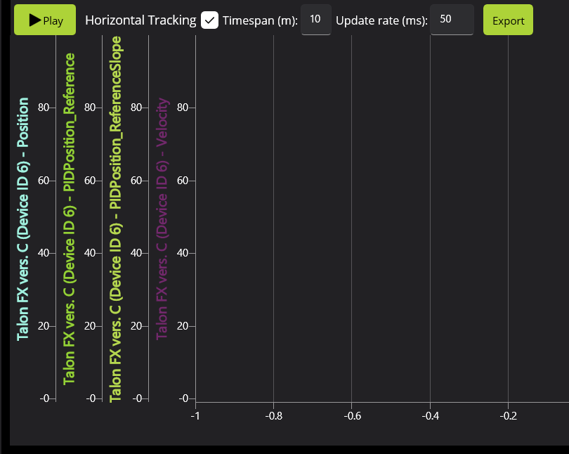
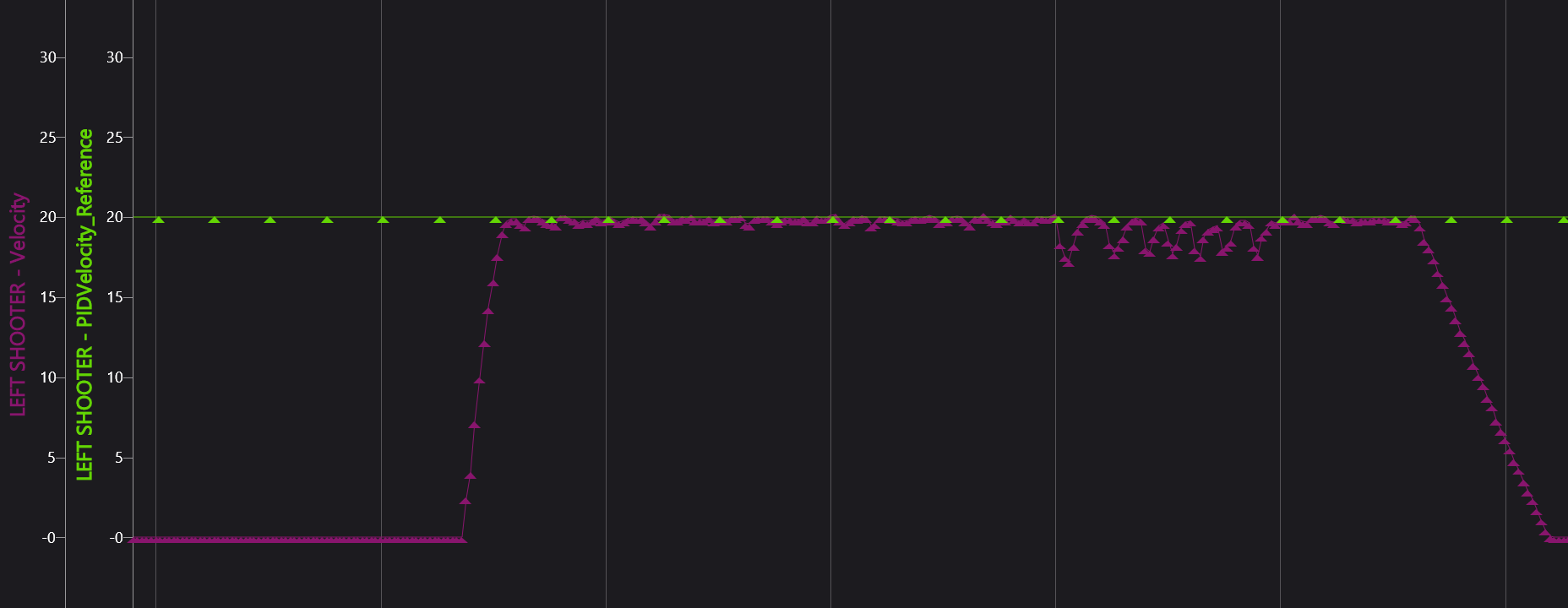
The Plot
|
In Phoenix Tuner, plot Velocity (rotations/sec) and Acceleration (rotations/sec2). |
|
Then also plot Reference (rotations/sec) and ReferenceSlope (rotations/sec2).
Make sure the Reference and ReferenceSlope are from PIDVelocity (not PIDPosition)
Gain Configurations
Motion Magic
-
Start with the MotionMagic configs
-
We don't use the cruise velocity gain in a velocity profile because we are trying to get to a target velocity, not this velocity we are setting
-
Make cruise acceleration 4, and double from there after more tuning
-
FeedForward and FeedBack
Try to minimize the amount of feedback gains while tuning, but use them if necessary
-
kS
-
Set to 1 and start doubling (use binary searching to get the optimum value)
-
We are trying to get the smallest kS possible before the motor starts turning
-
-
kA
-
Change it based on the Reference and our current Velocity signals
-
The steeper the slope of the Reference, the more we have to increase kA in order to get the Velocity to match it
-
A steeper slope means a higher kA and vice versa
-
-
kV
-
After getting the Velocity to peak along with Reference, it's time to raise kV
-
Increase kV until the Velocity line stays straight and is closely matching the Reference
-
These should get you pretty close to the Reference line - change kP and kD a little bit to get to your desired accuracy!
Specifics for Flywheel Tuning
While tuning flywheels, we are trying to get the motor to get to its target as fast as possible. When a game piece (such as a ball) goes through it, it should take as little time as possible to ramp back up to speed.
-
To do make the motor reach its target faster, keep on doubling the Cruise Acceleration until it reaches the speed quickly
-
For Rebuilt, we decided that less than a quarter second was optimal for reaching the target
-
Decrease kS and kA little by little until the initial ramp up speed matches the profile (doesn't have to be perfect)
-

-
To make the motor ramp back up quicker, you have to tune other gains a little more
-
If game pieces are going through in quick succession as the velocity slows down by a lot, then you need to increase kP and kD
-
Double kP a couple times until the motor doesn't dip as far down in velocity
-
If there is too much oscillation now, increase kD a little bit
-
-
Remember: kP makes the motor move faster if the error is bigger, and kD resists changes to the motor's velocity
-
-
For Rebuilt, we decided that less than a 10th of a second was good for the motor to ramp back up to speed
-
Shooting Our Shot
Shooting Our Shot - How to Create an Interpolating Tree Map
An Interpolating Tree Map (aka a Shooter Map) boiled down to its core is just linear regression. It was highly used during the Rebuilt Season for shooting into the hub and shuttling across the field.
For linear regression to work, it needs a bunch of data points. In the case of Rebuilt, the Shooter Map used the distance to the center of the hub as the input and it gave us the target rps for the shooter as the output.
Setting up the Map
To begin, you first need to manually find a bunch of good data points. We used the spots on the field where we would most often shoot from to determine our initial data points. Using these data points, we made a line graph on Google Sheets, and this helped us see where we were missing data. After this, we tested shooting with the shooter map automation and added in more data where the map failed.
The Code
The following are examples of code that was used during Rebuilt to setup our Shooter Map:
ShooterStateData.java in the util folder
package frc.robot.util;
import static edu.wpi.first.units.Units.Radians;
import edu.wpi.first.math.interpolation.Interpolator;
import edu.wpi.first.units.measure.Angle;
public class ShooterStateData {
public static final Interpolator<ShooterStateData> interpolator = (startValue, endValue, t) -> {
double initialHood = startValue.hoodPos.in(Radians);
double finalHood = endValue.hoodPos.in(Radians);
double initialRPS = startValue.rps;
double finalRPS = endValue.rps;
double initialToF = startValue.timeOfFlight;
double finalToF = endValue.timeOfFlight;
double interpolatedHood = initialHood + t * (finalHood - initialHood);
return new ShooterStateData(
Radians.of(interpolatedHood),
initialRPS + t * (finalRPS - initialRPS),
initialToF + t * (finalToF - initialToF));
};
public final Angle hoodPos;
public final double rps;
public final double timeOfFlight;
public ShooterStateData(Angle hoodPos, double rps, double timeOfFlight) {
this.hoodPos = hoodPos;
this.rps = rps;
this.timeOfFlight = timeOfFlight;
}
}
Initializing the Shooter Map in ShooterConfigsBeta.java
public static final InterpolatingTreeMap<Double, ShooterStateData> SHOOTER_MAP =
new InterpolatingTreeMap<>(InverseInterpolator.forDouble(), ShooterStateData.interpolator);
Logging Distance to Hub in Robot Container
public void updateLoggers() {
Pose2d currentPose = drive.getState().Pose;
Translation2d modifiedTarget = AllianceFlipUtil.apply(centerHubOpening.toTranslation2d());
Translation2d currentPosition = currentPose.getTranslation();
double distance = modifiedTarget.getDistance(currentPosition);
Logger.recordOutput("AutoAimCommands/Shooter Map/hub distance", distance);
}
Putting data into the Shooter Map (this is also in ShooterConfigsBeta.java, right underneath the initialization)
static {
SHOOTER_MAP.put(1.74, new ShooterStateData(HoodPositions.STOW.getPosition(), 25, 0.0));
SHOOTER_MAP.put(2.13, new ShooterStateData(HoodPositions.STOW.getPosition(), 27, 0.0));
SHOOTER_MAP.put(2.43, new ShooterStateData(HoodPositions.STOW.getPosition(), 30, 0.0));
SHOOTER_MAP.put(2.78, new ShooterStateData(HoodPositions.STOW.getPosition(), 31, 0.0));
SHOOTER_MAP.put(3.15, new ShooterStateData(HoodPositions.STOW.getPosition(), 33, 0.0));
SHOOTER_MAP.put(3.78, new ShooterStateData(HoodPositions.STOW.getPosition(), 38.7, 0.0));
SHOOTER_MAP.put(4.36, new ShooterStateData(HoodPositions.STOW.getPosition(), 44, 0.0));
}
Using the Shooter Map to actually calculate the target rps of the Shooter (in AutoAimCommands.java)
public static Command readyAim(CommandSwerveDrivetrain drive, Shooter shooter, Translation2d target) {
return Commands.defer(
() -> {
Pose2d currentPose = drive.getState().Pose;
Translation2d modifiedTarget = AllianceFlipUtil.apply(target);
Translation2d currentPosition = currentPose.getTranslation();
double distance = modifiedTarget.getDistance(currentPosition);
ShooterStateData state = ShooterConfigsBeta.SHOOTER_MAP.get(distance);
double targetRPS = state.rps;
Logger.recordOutput("AutoAimCommands/Shooter Map/target rps", targetRPS);
return shooter.shoot(targetRPS);
},
Set.of(shooter));
}The Shooter Map uses the distance to the hub the input, it does the linear regression, and then outputs the target rps.
Once you have set everything up, you'll be able to call the readyAim command using a controller binding and it'll work!
Calibration and Cows
Calibrating your robot to a specific field is vital to ensure that your localization, autos, and auto-align functionality remain accurate and consistent. This chapter will discuss the intricacies of field calibration and some methods to do it, as well as how cows are involved.
WPIcal (infused with holiness)
Here are the docs I will be mostly referencing on this page:
https://docs.wpilib.org/en/stable/docs/software/wpilib-tools/wpical/index.html
WPIcal is a tool made by the ever-lovely Worcester Polytechnic Institute based off of Cow-libration (see future pages) that help your robot understand where it is and account for small variations in tag placements.
Calibrate your camera
Start by filming a video with your camera of a ChArUco board (with an odd height if you choose the OpenCV option) making sure to capture various angles to ensure proper calibration.
Example video: Video of online ChArUco board to calibrate camera
A ChArUco board can be generated from this link: calib.io
After filling out all the fields on WPIcal and selecting Calibrate, check the video displayed and if any squares aren’t detected or there’s other weird looking stuff film your video again.
Film your videos
When filming videos of the field, you need at least two AprilTags in each video, and it is preferred if there are more. Don’t sacrifice quality for quantity though, you want WPIcal to still identify the tags you’re filming.
Make sure to always “connect” your videos by having tags in common between them. For example, if your first video is of tags 1, 2, & 3, your next video should include at least one of those three days so the relative distances can be calculated.
Calibrate each pinned tag
Before uploading the ideal field map, double check what type of field (ie. AndyMark or welded) is being used at the competition or field you’re calibrating.
You can select which tags are calibrated using the field calibration of WPIcal if only some AprilTags are needed to be more accurate.
After the calibration, select “Visualize calibration” to compare your tags and check that there aren’t crazy differences between the original position and the calibrated position.
Finally, take the final field calibration json and put it in your code to use!
Cowlibration
Cowlibration is a field calibration tool developed by FRC team #1538, The Holy Cows.
https://github.com/TheHolyCows/cowlibration-field
Flashing Limelights
You've finally gotten hands on a Limelight to use for vision. Yay! Now, you want to know how to flash the Limelight so you can configure it for your robot. Here's an easy guide for that:
First, download the Limelight Hardware Manager from here, along with the correct operating system file for the type of Limelight you plan to flash: https://docs.limelightvision.io/docs/resources/downloads
Next, follow the Quick Start instructions for your specific Limelight to find the config button that you hold down, while plugging into your Limelight over USB. For example, the Limelight 4's config button is hidden inside this tiny hole, that we had to press down with a screwdriver.
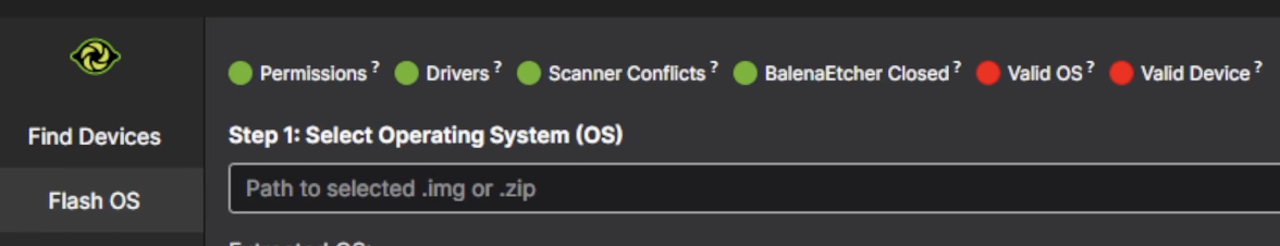
[INSERT PHOTO HERE]
Then, switch the Flash OS section of the Limelight Hardware Manager app, and install your drivers if you haven't already. You'll know when your drivers are installed when you see the Drivers dot turn green at the top of the bar.
Additionally, if you have balenaEtcher installed from flashing previous SD cards, please make sure you close it!
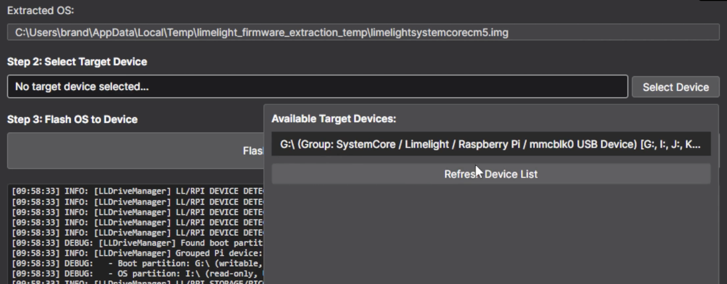
Afterward, select your OS's .img or .zip file, make sure the extracted OS is correct, and then select your target device.
Finally, just hit the green Flash Device button and wait for this notification!
Once you get this notification, you are done!
Here are the links to other resources if you still need any more help!
Video Guide for Flashing: https://vimeo.com/1157367762?fl=pl&fe=cm
Limelight 3 Docs: https://docs.limelightvision.io/docs/docs-limelight/getting-started/limelight-3#4-updating-limelightos
Limelight 3G Docs: https://docs.limelightvision.io/docs/docs-limelight/getting-started/limelight-3g#4-updating-limelightos
Limelight 4 Docs: https://docs.limelightvision.io/docs/docs-limelight/getting-started/limelight-4#4-updating-limelightos
Limelight Cowlibration
If you are calibrating a Limelight Camera check the limelight vision docs linked below:
Autonomous Adventures
There are 3 ways we can create autos on YETI:
- PathPlanner
- Choreo
- Composable Functions
This chapter will guide you through using each of these tools to create autonomous paths.
PathPlanner
Overview and Resources:
PathPlanner is a pathing tool developed by team #3015 and is fairly easy to use because of its intuitive, visual nature.
Here are the docs: https://pathplanner.dev/home.html
This page will show you how to effectively use the tool: https://pathplanner.dev/gui-editing-paths-and-autos.html
If you have any questions, consult the docs first. They usually contain the answers you desire.
Some of the most important aspects of PathPlanner are:
Paths vs. Autos:
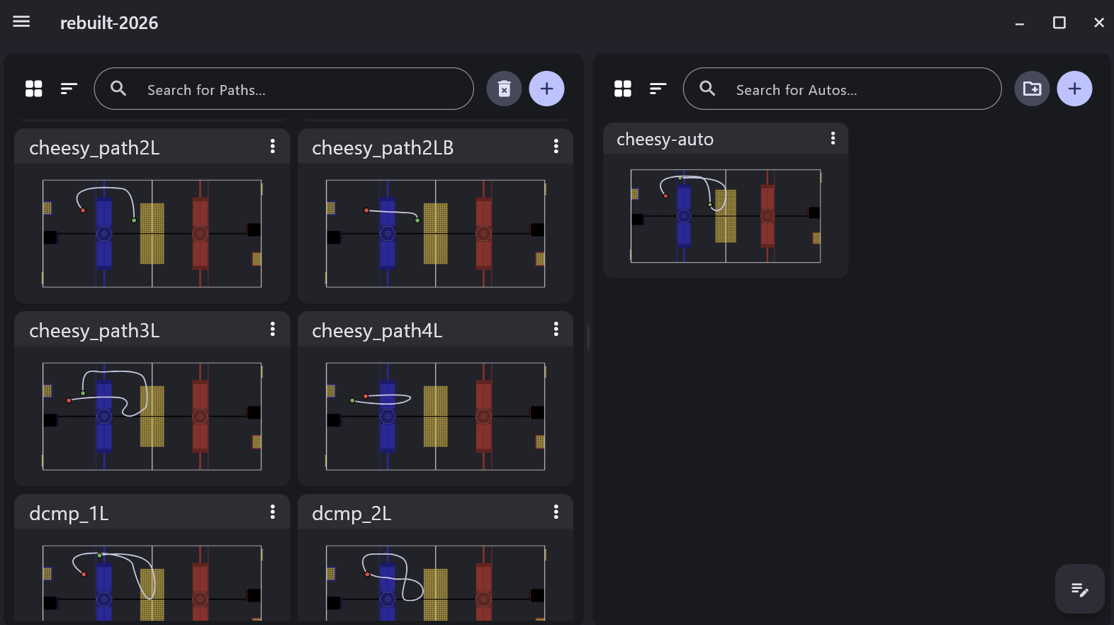
To put it simply, multiple paths make up an auto. In the picture below, the paths are individually built on the left side, while the auto is on the right side, named "cheesy-auto." In this case, "cheesy-auto" contains both paths "cheesy_path2L" and "cheesy_path3L," allowing us to split up the behaviour of our entire autos easily into distinct paths. We can change paths without interacting with the entire auto, making iteration and tuning simple.
Making a Path:
To create a path, PathPlanner includes many tools that make the process easier. Below is a description of those tools to streamline your building.
Rotation Targets:
Rotation targets define points along the path where the robot should target a given rotation. When path following, the robot will look ahead for the next rotation target, then attempt to rotate to its associated rotation. Rotation targets can be edited in the rotation targets tree. This is only available when holonomic mode is on.
Essentially, this means that you can dictate what direction the robot is facing at any point along the path. This is useful in cases when you want to point your intake towards game pieces on the floor, as many teams did with the notes in 2024.
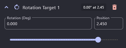
You can use the Rotation (Deg) box to change the heading of the robot and the position slider or the Position box to change at what point along the path you want the robot to be at that heading.
Event Markers
Event markers define points along the path where other commands should be triggered while path following.
This means that you can run custom commands, such as intake or shoot, at desired points along the path. Check the docs for further instructions regarding this.
Waypoints & Linked Waypoints
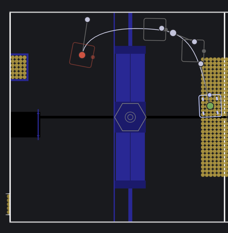
Waypoints are points that your robot will follow to connect a path. In the picture above, the robot has a start, end, and two additional waypoints along its path, indicated by different colors. Add them as necessary to allow your robot to move to the desired position and avoid obstacles.
A good rule of thumb is to use as few waypoints as needed to decrease complexity and the time it takes your robot to travel from start to end.
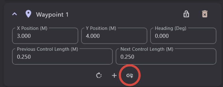
Linked Waypoints are universal points on the field that can be used in any path. For example, if you know an optimal shooting position, create a waypoint at coordinates (x: 3.0, y: 4.0), and make it a Linked Waypoint using the button shown below. You can now use this linked waypoint in other paths by searching for it by its name. Editing a linked waypoint after it has been created will change the position of that waypoint for all instances on any path.
Other Important Aspects to Consider
- Path Optimization
- Command Groups
- Global Constraints
Choreo
Overview and Resources
This tool was created by a developer group called Sleipnir
Here are the docs for Choreo: https://choreo.autos/
This guide will walk you through how to use Choreo: https://choreo.autos/usage/editing-paths/
This page will be further updated as we start to use and experiment with Choreo!
Pathplanner vs Choreo
Overview
Pathplanner and Choreo are two solutions to generating paths in the autonomous period, and they are quite similar in many respects. At the time this page is being written (Summer 2025), YETI doesn't have experience with using Choreo. Therefore, it is important to understand the distinction between the two tools and their potential advantages and disadvantages when making decisions on what to use.
Fun Fact: FRC #3015- the team that created Pathplanner- actually uses Choreo instead of Pathplanner!
CD Threads: https://www.chiefdelphi.com/t/choreo-vs-pathplanner/467373
https://www.chiefdelphi.com/t/choreo-vs-pathplanner/492427
Composable Functions
Overview
Using composable functions essentially means ordering commands and paths into autos that are created as commands. This is, after some consideration, what YETI prefers to use to create autos. It is important to note that, while commands are created and used normally, paths have to be created through PathPlanner or Choreo.
Walkthrough
Here is an example of an auto we used in 2025:
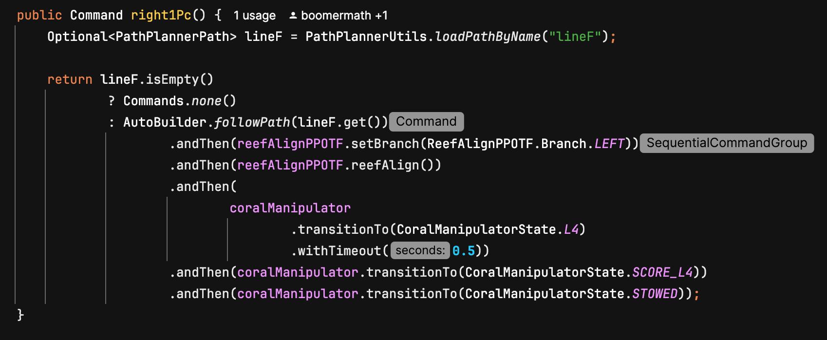
As you can see, the auto- right1Pc- is actually a command. The first thing we do is define lineF, which is a path from PathPlanner. The next step is to make sure the path exists, and when it is confirmed, start creating the auto. In this case, the first thing we do is follow the lineF path, but we can switch it around with other commands in any order that we deem desirable. We use other commands normally.
Note that paths are not the only way for the robot to drive around. As you can see, we use our auto-align command, which translates and rotates the robot to point towards our target.
Happy auto-making!!!
Tips for Automaking
Overview
Making autos can be hard. This page will go over some tips on how to effectively create and improve autos.
Tips and Stuff:
Initial Orientation and Tag Visibility: So, one afternoon (literally the day we had to pack for world champs lol) in 2025, we were trying to finish an auto we were working on, but it kept messing up at the beginning of the path. When we looked at AdvantageScope, we figured out why: the localization was super inaccurate until it was able to see an April Tag. Basically, this means that the robot was struggling to figure out where it was on the field when it was unable to see a tag. We tried many complicated methods, but to no avail. Eventually, we simply rotated the robot's starting position so that it was able to see an April Tag at the start of the auto. This immediately fixed the problem. The moral of the story is to be mindful of what your cameras can see and look for simple solutions first.
Speed vs Functionality: When making autos, you might be tempted to speed them up as soon as possible so that you can get as many points as possible in the 15 seconds you have. However, you should prioritize functionality and consistency over speed. Follow this guide when making autos:
-
Make your auto do an action consistently
-
Wanna add another action? Do it, and make sure it works consistently.
-
Does the combination of those actions take longer than 15 seconds? Find places where you can speed things up. Increase the velocity and acceleration of the paths. Reduce or remove wait commands. Basically, just minmax until it fits within the time limit.
-
Go to Step 2
Simulation
This chapter details how to use simulation effectively to develop code without a physical robot, or to aid in tuning with a physical robot.
Using CAD in AdvantageScope
Overview
Simulation is very important for YETI, allowing us to test and develop code without a physical robot. Being able to use the CAD created by our team members simulates the actual hardware and can be used to troubleshoot more precisely. The documentation AdvantageScope provides is extremely thorough and it’s always recommended to read the source material. Much of the information found on this page is derived from these docs.
Exporting from SolidWorks
In order to accurately simulate the many moving parts of a robot, the files themselves must be separate. Anything that is an “articulated component”, that provides a degree of freedom and moves independently, such as an elevator, arm, or wrist should be in its own file, and exported as such.
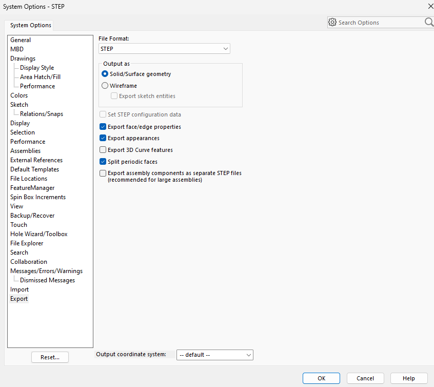
The settings to properly export a component with color are shown below:
Converting to .glb
AdvantageScope uses .glb files for 3D models, and while SolidWorks can export CAD files in that format, the files are often very large and we prefer to first export as STEP and later convert to .glb.
A STEP by STEP :) tutorial for conversion using the application CAD Assistant can be found here.
Configuring the Robot
Configuring your individual components is arguably the most important step, as without doing so you just have a bunch of floating arms and a robot that looks vaguely like a Roomba.
Below is the format the config.json file should be in:
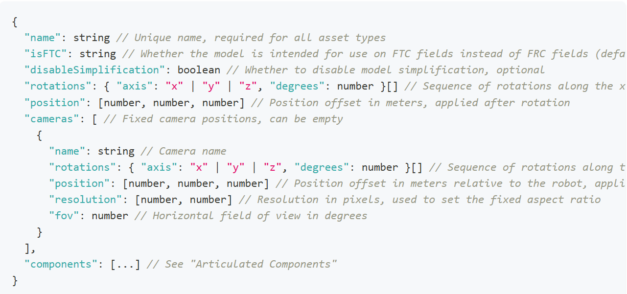
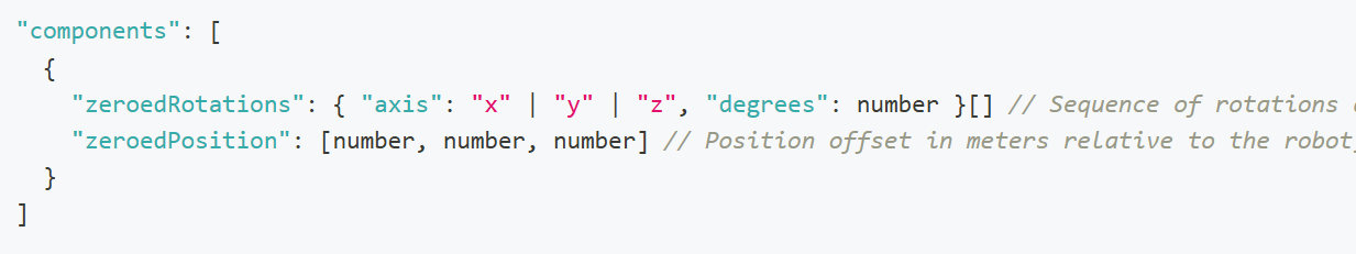
Do note that anything in the above format that looks like {something something} [] is a list where you add elements in the format of {something something}. Namely, the rotations are a sequence that contains only the axes that require rotation.
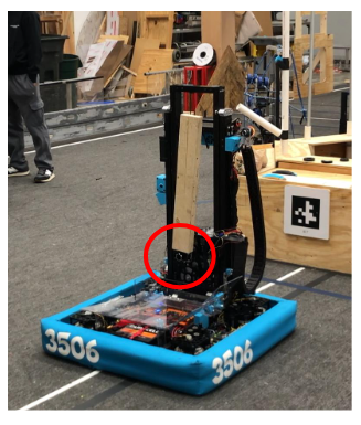
To configure the components, the exact measurements for the positions of the components are needed.
Here, the zeroed position of an arm (portrayed as a wooden block) is circled in red.
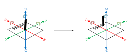
First, the model of the arm must be rotated until it is oriented correctly relative to the robot. If the arm in the file were “lying down”, it would have to be rotated along the y axis, 90 degrees to make it point upwards.
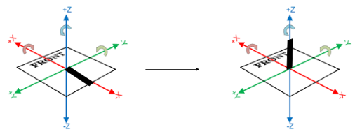
"zeroedRotations": [ { "axis": "y", "degrees": 90} ]
Using the actual measurements of the robot, whether in real life or from CAD, you can fill out the “zeroedPosition” list. In this case, the joint at which the arm is connected is x centimeters back from the center of the robot (on the x axis) and z centimeters up from the base (on the z axis). It’s already centered with the robot “left and right” so there is no translation needed on the y axis.
"zeroedPositions": [x, 0, z]
The component for the arm would be
{
"zeroedRotations": [
{ "axis": "y", "degrees": 90}
],
"zeroedPosition": [x,0,z]
}
This process should be repeated for all other components, and the file names of each component model should be “model_INDEX.glb”, the index being that of the component in the array “components” beginning at 0.
A video for all this can be found in the docs for Custom Assets in AdvantageScope that were linked at the beginning of this page: here.
Simulating Beluga in the Sim Sandbox
Setting Up AdvantageScope
To get AdvantageScope, you can download the version for your operating system here: https://github.com/Mechanical-Advantage/AdvantageScope/releases
Then, follow the installer instructions for your system. Please install the latest stable release, and not the beta versions.
After opening AdvantageScope, go to App > Show Assets Folder. Note that if you are using the alpha release of AdvantageScope for Systemcore testing purposes, you will need to go under the AdvantageScope menu instead of Help. This will show you in Finder/File Explorer where the path of your assets folder is. You will need to know this for the next steps.
Getting Beluga in AdvantageScope
To get Beluga into AdvantageScope, download this .zip file from the YETI Shared Drive: https://drive.google.com/file/d/1L-IlO6yLEO3EWTT7hQ3TDLUFpgTqMgc7/view?usp=drive_link
If you are not part of the shared drive, please contact Mrs. Iaiela Dumitrescu to be added.
Extract the Robot_Beluga folder, and copy this into your assets folder that you found in the previous steps.
You will use Beluga when using the Sim Sandbox.
Getting Started with the Sim Sandbox
To get started, make sure you have git installed. If not, get it from this link for your operating system: https://git-scm.com/downloads
Go to the sim-sandbox repository on the YETI GitHub, or use this link: https://github.com/yeti-robotics/sim-sandbox. Then, click on the "Use this template" button in the top right hand corner. Click "Create new repository," and pick a name for it. Make sure to check the box that includes all branches! This will create your own repository with all of the template files to start.
Next, open up IntelliJ and head over to File > New > Project from Version Control. Select the Git option, and then paste in the URL of your repository, which you'd get from pressing the green "Code" button when you go to the repository in your browser, and copying the URL that you find in the little dropdown beneath it. It should look something like this
https://github.com/YOUR_GITHUB_USERNAME/REPO_NAME.gitYOUR_GITHUB_USERNAME should be replaced with your GitHub username, and the REPO_NAME should be replaced with whatever you decided to name the repository when creating it. Once you hit the "Clone" button, this will download everything onto your device.
Open up the project folder in IntelliJ. Then, you can start up your development work as normal by letting Gradle download the dependencies. Afterwards, go to the Gradle menu, and go under the tasks in the other folder. You should then find the simulateJava task. Run that task to open the simulator window.
Connecting the Simulator to AdvantageScope
Now that you've opened the simulator, let's start by configuring it. You're going to see an interface that looks something like this:
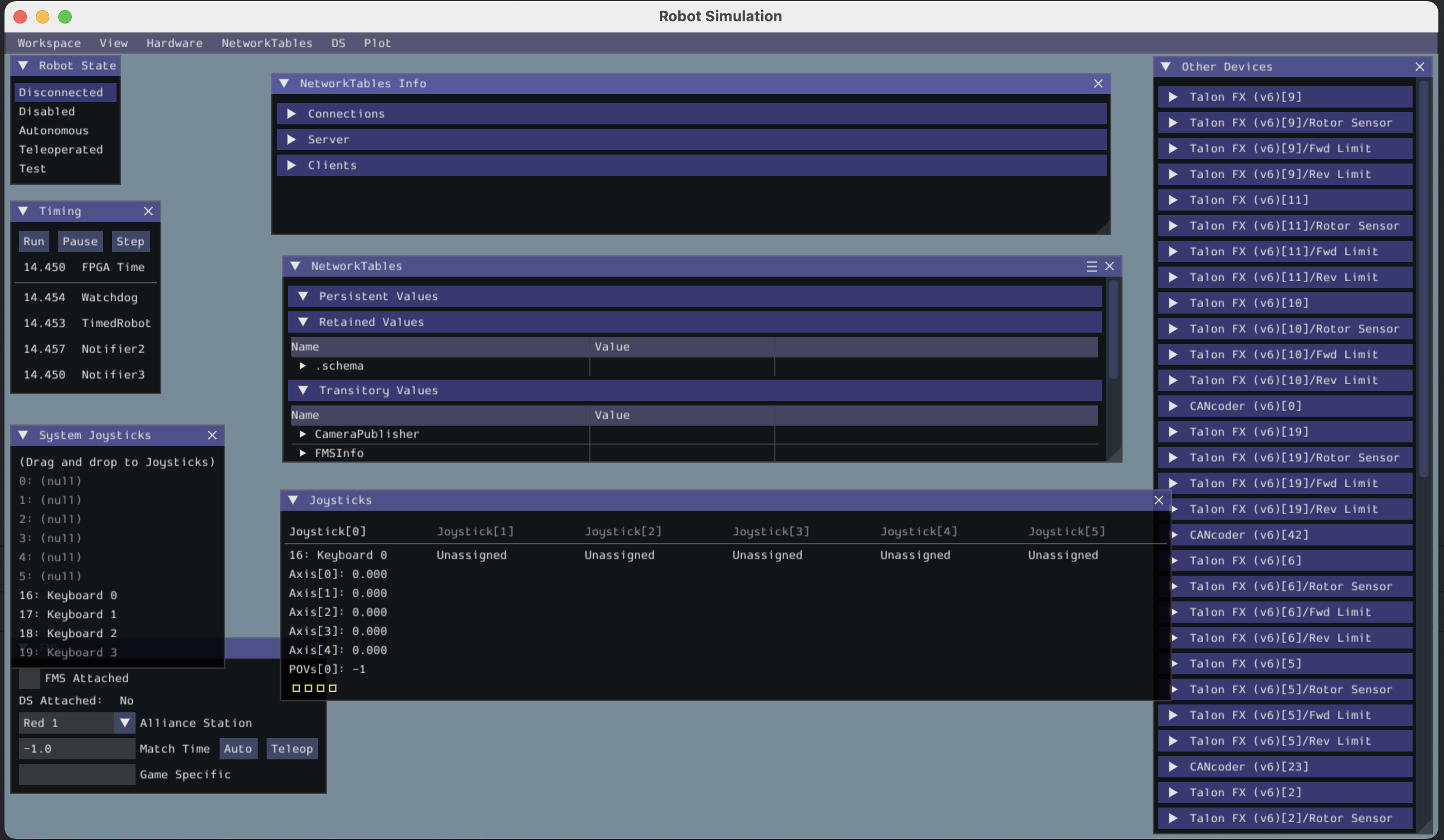
Let's connect our keyboard to the joystick port so we can drive the robot in simulation later. Under System Joysticks, drag Keyboard 0 on top of Joystick 0. Mine has already been configured as seen in the picture above, but you will need to do that on first launch.
Next, let's enable the robot. Under Robot State, hit the Teleoperated button.
Now, let's go back to AdvantageScope. It'll look something like this on first installation:
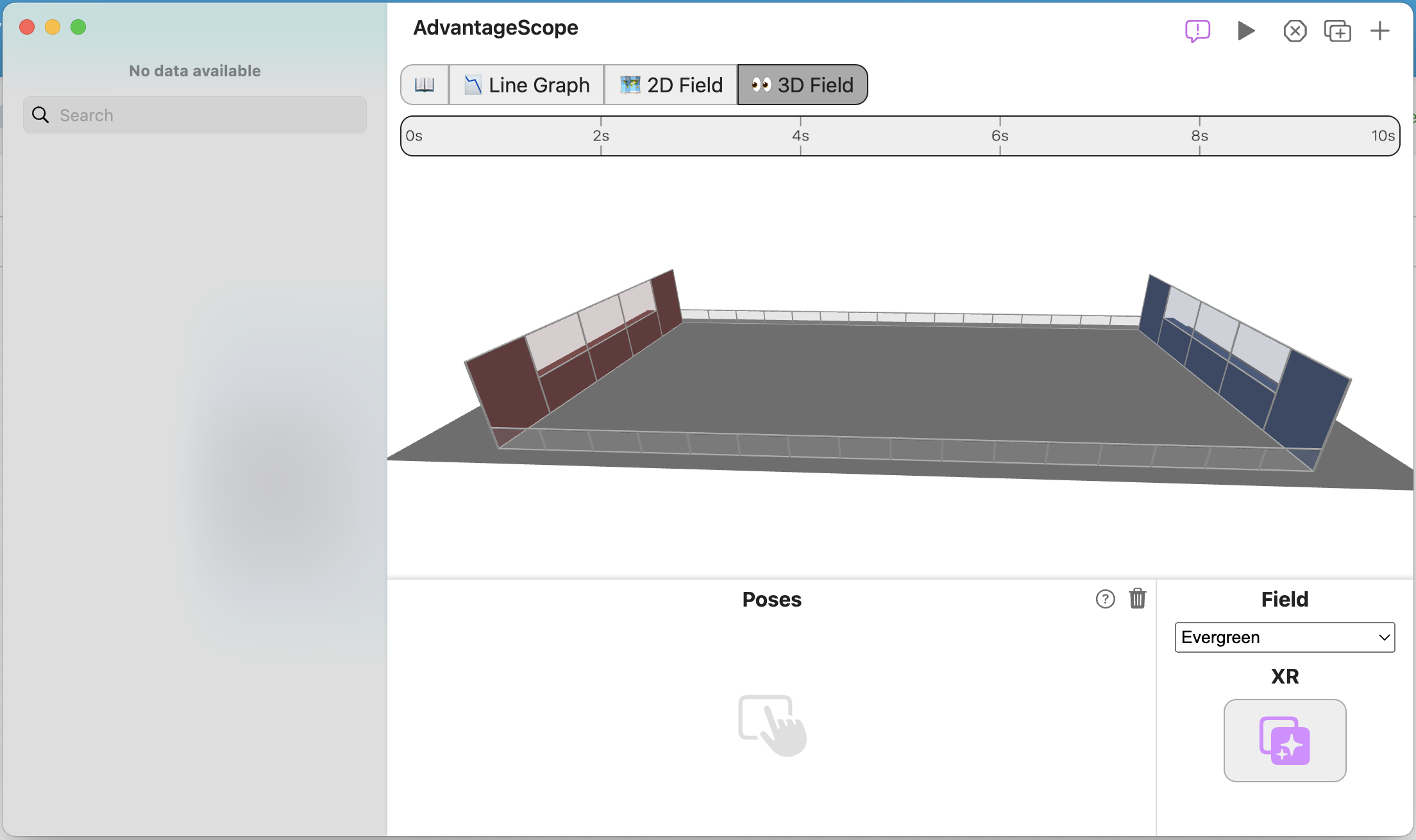
This isn't the right field. Let's change that! Under Field, click the dropdown that currently is Evergreen. Change the field to 2025 Field (Welded). That looks better! Now, if you're a Windows user, press Ctrl + Shift + K to connect the simulator to AdvantageScope. If you're a Mac user, press Cmd + Shift + K to connect the simulator to AdvantageScope. Your window should now look something like this:

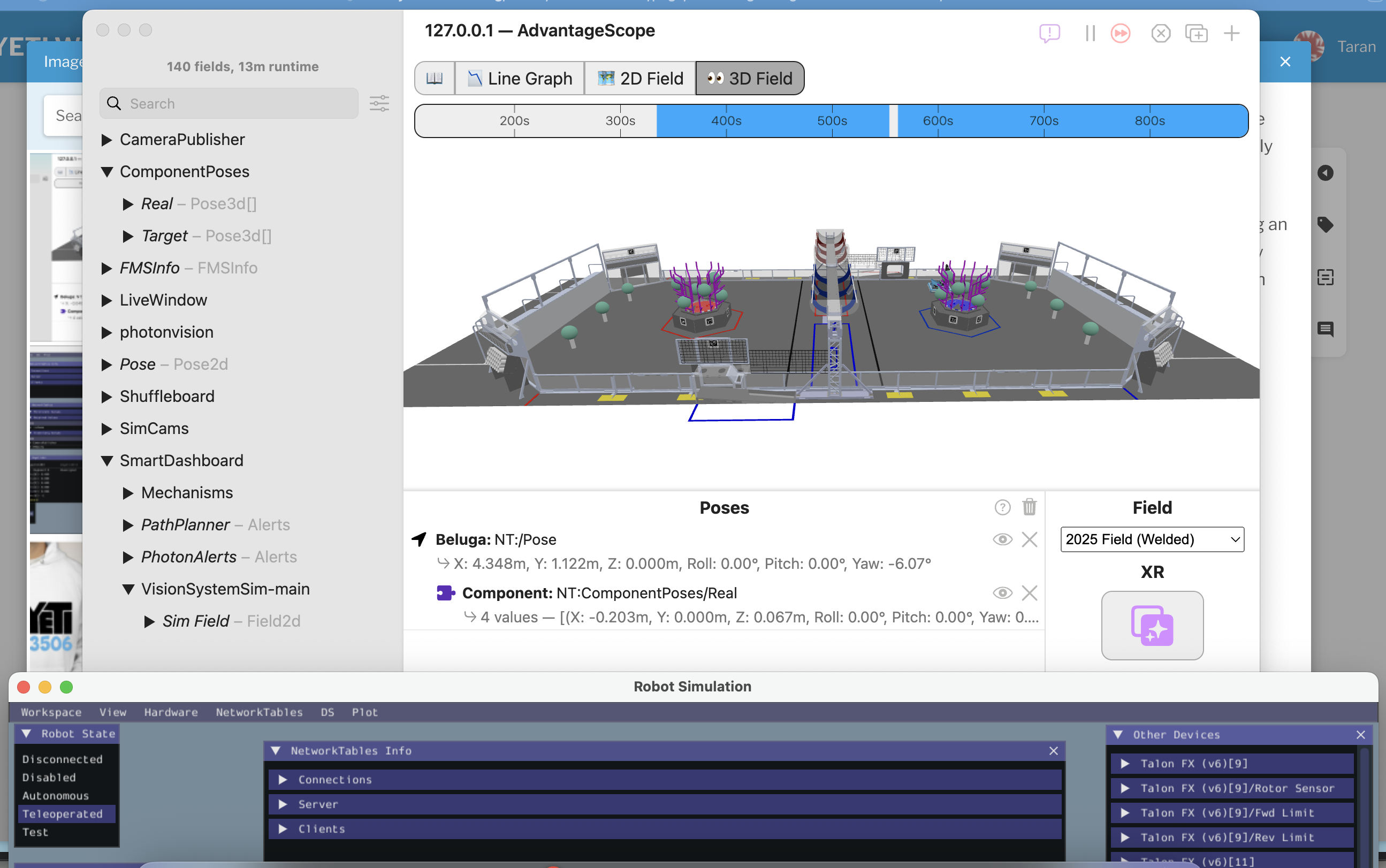
Now, we're missing the robot. Grab the Pose - Pose2d object and drag it into the Poses area underneath the 3D field. You should now see something like this:
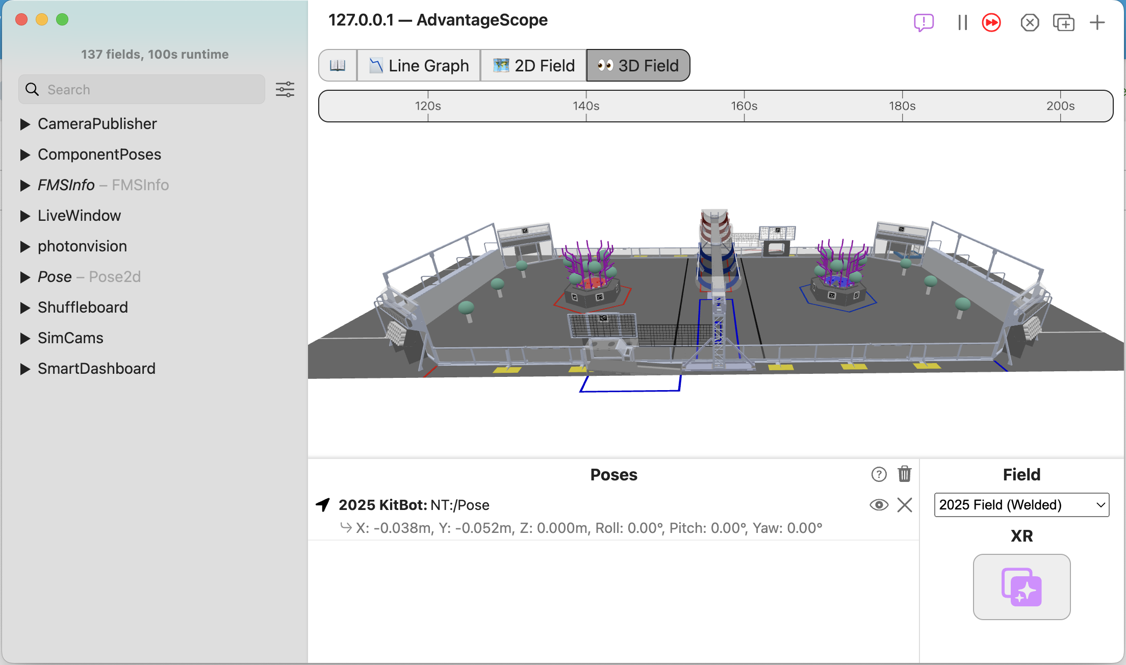
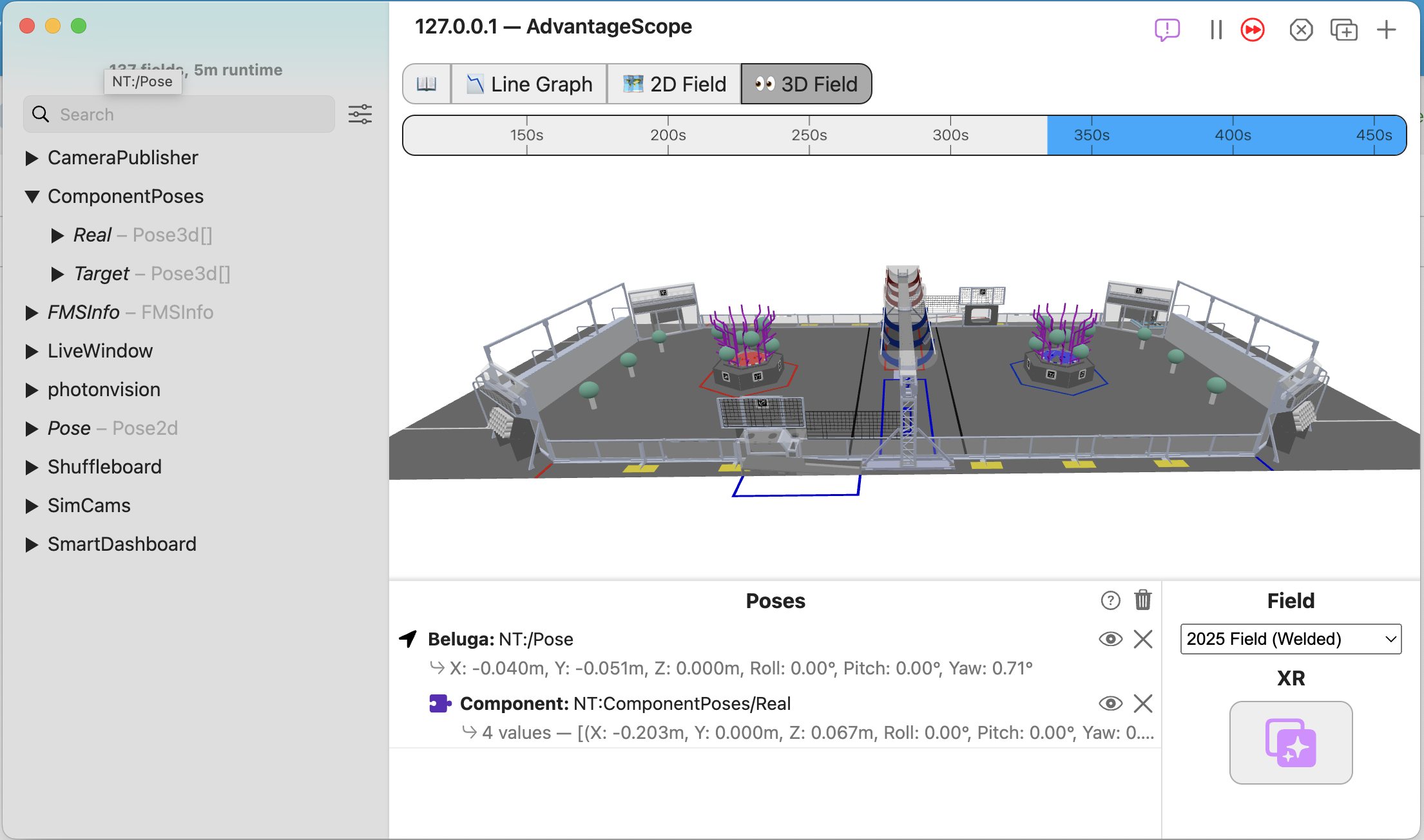
Hold up. This isn't our robot. Let's change that! Right click on 2025 Kitbot and select Beluga instead from the dropdown menu. That's better. Now, we need to add Beluga's components, like the elevator, arm, and wrist. Open up the ComponentPoses dropdown in the sidebar. You should see 2 different items, Real, and Target. It'll look something like this:

Now, drag and drop the Real object on top of Beluga. This should look something like this afterward:
That's it! You now have Beluga on your field. Finally, let's get the robot driving around the field!
Driving Beluga in Simulation
Go back to your simulation window. Now, you can use the WASD keys on your keyboard to start driving Beluga around. You'll see the robot move on the field. You will need to keep the simulation window in focus when driving the robot around. The best way to do this is by dragging the simulation window to the bottom of the screen, just keeping the title bar in frame so you have something to click to keep it in focus, and then keeping AdvantageScope up top. It'll look something like this:
That's it! Now you have a robot driving around in simulation! If you have any questions, feel free to reach out in the Programming channel on Discord. There's always someone around to help you out! After setting this sandbox up, try and code out some of the mechanism commands, like for the elevator, arm, and wrist. Good luck!
Integrating MapleSim
What is MapleSim?
MapleSim is a physics simulator that allows your robot to interact with its surroundings on the game field. This means that the robot will be able to interact with game pieces, obstacles, and other field elements.
Why use MapleSim?
- Test autos
- Fine tune advanced teleop enhancement features such as pathfinding-auto-alignment
- Optimize shooters and other mechanisms using data collected from simulated mechanisms
- To do all of this without the hassle of a real bot
Tips for Comp/Pit Crew/Drive Team
It's important to know how to deal with problems or talk to judges at comp. This chapter will cover a couple tips about behaving at comp.
Tips for being a Programmer at Comp
Troubleshooting
-
- Whenever facing unknown problems at comp, the first thing to do is check the match logs and replay them in AdvantageScope. This will likely reveal the nature of the issue you face, whether it be excessive CPU usage or driver error.
- When you figure out the issue and believe that it is fixed, it is generally a good idea to simulate and make sure that it works. This is especially useful when the change you made impacts the logic of the robot or the autonomous paths.
- If the issue is CPU usage (usually characterized by driver input delay or comms issues), you can check to see what is taking too much load by profiling with VisualVM. This will give you insight as to what is taking too much load (for us, it was either vision or logging-related) and allow you to fix it before the next match.
Talking to Judges
-
-
- Usually, only selected pit crew members talk to judges, so if you're one of them, make sure you review the whole code structure and be aware of the kinds of tools and techniques we use to automate our robot. Judges love to hear about how we can effectively reduce human error.
-
Drive Team
-
- If you're on drive team, there are a couple of things you should know how to operate on the DS laptop:
- Driver Station: Know how to connect and organize controllers in the USB devices tab, open and check logs and console messages, and disable the robot.
- Pathplanner/Choreo (if we are using it): Sometimes, there is discussion between alliance partners of which team will run which of their autos, and it's good to be able to show your partners what path your autos take to help maximize autonomous point gain. Make sure you can navigate the autos and paths, and also make sure you know what the autonomous and path names are.
- PhotonVision: If this issue is not fixed, please make sure to toggle auto exposure. Please. Also, it's probably better to close any camera feeds to ensure it doesn't eat into the bandwidth.
- Elastic: This is your dashboard, and if you configure it effectively, you can display important information to keep an eye out for during a match. Know how to open and use Elastic and drag in new widgets.
- If you're on drive team, there are a couple of things you should know how to operate on the DS laptop:
Taking Advantage Kit
How to implement an Advantage Kit structure in code
Akit File Structure
Overall Structure
When implementing akit into your robot code, it is suggested you create four files: the configs file, the input output interface, input output class, and the subsystem file. For subsystems that move, such as an elevator, you also need an enum for positions. These will help to abstract and organize your code.

Configs File
This file lists out all the configurations for the motors and sensors in the subsystem. It includes tuning constants, motor and sensor IDs, motor configs, and any motion magic requests you might need.
Follow the naming convention of "(SubsystemName)Configs".
Subsystem configs example from a hood subsystem. It contains the IDs and other unchangeable information need for configuration.
public class HoodConfigs {
static final int HOOD_MOTOR_ID = 44;
static final int HOOD_CANCODER_ID = 45;
static final double GEAR_RATIO = 1;
static final double MAGNET_OFFSET = 0;
public static final double TEST_HOOD_SPEED = 0.2;Tuning configs for the k values and motion magic.
public static final Slot0Configs SLOT_0_CONFIGS = new Slot0Configs()
.withKP(2)
.withKI(0)
.withKD(0.5)
.withKA(1.1)
.withKV(0.4)
.withKS(11.5);
public static final MotionMagicConfigs MOTION_MAGIC_CONFIGS = new MotionMagicConfigs()
.withMotionMagicAcceleration(8)
.withMotionMagicCruiseVelocity(4)
.withMotionMagicJerk(0);Gear ratios and tuning constants should be put in a motor config object here.
static final TalonFXConfiguration TOP_MOTOR_CONFIGS = new TalonFXConfiguration()
.withFeedback(new FeedbackConfigs().withSensorToMechanismRatio(2.89).withRotorToSensorRatio(1))
.withSlot0(SLOT_0_CONFIGS)
.withMotionMagic(MOTION_MAGIC_CONFIGS);
static final TalonFXConfiguration BOTTOM_MOTOR_CONFIGS = new TalonFXConfiguration()
.withFeedback(new FeedbackConfigs().withSensorToMechanismRatio(2.89).withRotorToSensorRatio(1))
.withSlot0(SLOT_0_CONFIGS)
.withMotionMagic(MOTION_MAGIC_CONFIGS);An example of what a tuned canrange looks like. We have a guide to tuning them here.
static final CANrangeConfiguration CANRANGE_CONFIGS = new CANrangeConfiguration()
.withToFParams(new ToFParamsConfigs().withUpdateMode(UpdateModeValue.ShortRange100Hz))
.withFovParams(new FovParamsConfigs()
.withFOVCenterX(0)
.withFOVCenterY(0)
.withFOVRangeX(27)
.withFOVRangeY(27))
.withProximityParams(new ProximityParamsConfigs()
.withProximityThreshold(0.126)
.withProximityHysteresis(0.1)
.withMinSignalStrengthForValidMeasurement(2500));Input Output Interface
This interface is used to list what you want to log with akit and how you want to be able to control the devices in the subsystem. It includes a class of all the inputs being logged.
The interface should be named "(SubsystemName)IO".
Inputs class to signify what akit is logging (make sure to use the @AutoLog decorator):
public interface ClimberIO {
@AutoLog
public static class ClimberIOInputs {
public boolean isAtBottom = true;
public double position = 0.0;
public double targetPosition = 0.0;
}Because this is an interface (outside of the ClimberIOInputs from earlier), none of these methods should have any code in them. Each method should have the void return type and default keyword - they will only be using control requests when implemented. Every interface needs to include the updateInputs method. This will be used to actually log the inputs.
public default void updateInputs(ClimberIOInputs inputs) {}
public default void setClimberPosition(Angle position) {}
public default void zeroPosition() {}
public default void neutralizeClimber() {}
public default void applyPower(double percent) {}
}Input Output Class
This class implements the interface from before. It delineates what the subsystem is able to do, which should already have been decided in the interface.
Name it "(SubsystemName)IO(RobotVersion)". This is the only class that needs a new version for each robot version you have. So you might have a ShooterIOAlpha and a ShooterIOBeta.
Declare any devices and control requests in this class. Notice the use of the implements keyword.
public class ClimberIOAlpha implements ClimberIO {
private final TalonFX climberMotor;
private MotionMagicTorqueCurrentFOC magicRequest = new MotionMagicTorqueCurrentFOC(0);
private DutyCycleOut dutyRequest = new DutyCycleOut(0);Initialize all devices in the constructor. The if statement is used to add devices to the simulation when the robot is being simulated. You also need to add the configurations from the configs class to the motors and sensors.
public ClimberIOAlpha() {
climberMotor = new TalonFX(ClimberConfig.CLIMBER_MOTOR_ID, Constants.rioBus);
if (Robot.isSimulation()) {
PhysicsSim.getInstance().addTalonFX(climberMotor);
}
climberMotor.getConfigurator().apply(ClimberConfig.primaryTalonFXConfigs);
}This is the implementation of the updateInputs method. The values you want to be updating are those declared and initialized in the SubsystemIOInputs class of the interface. The @Override decorator is needed for all methods in this class.
@Override
public void updateInputs(ClimberIOInputs inputs) {
inputs.position = climberMotor.getPosition().getValueAsDouble();
inputs.targetPosition = climberMotor.getClosedLoopReference().getValueAsDouble();
}This is the main part of the class. Every method you wrote in the interface will be implemented here. Make sure to use the @Override decorator for each method and to keep the exact same signature as you had in the interface. Each method returns nothing, only dictating how a motor can be controlled.
@Override
public void setClimberPosition(Angle position) {
climberMotor.setControl(magicRequest.withPosition(position));
}
@Override
public void zeroPosition() {
climberMotor.setPosition(0);
}
@Override
public void neutralizeClimber() {
climberMotor.setControl(new NeutralOut());
}
@Override
public void applyPower(double percent) {
climberMotor.setControl(dutyRequest.withOutput(percent));
}
}Subsystem Class
The subsystem class uses the IO class to execute commands to run the motors as you specify. This is what will be used in RobotContainer.
Named "(SubsystemName)Subsystem".
Make sure to extend SubsystemBase to be able to use certain methods. Make an instance of the IO class you just created called "io". The second object is an instance of a class that is named the same as the class you created in the interface with "AutoLogged" at the end. It will throw an error until you build.
public class ClimberSubsystem extends SubsystemBase {
private ClimberIO io;
private ClimberIOInputsAutoLogged inputs = new ClimberIOInputsAutoLogged();The constructor should take a parameter of the IO class you made earlier. Assign it to the io object you declared in this class. Additionally, any triggers you might need should be created in the constructor.
public Climber(ClimberIO io) {
this.io = io;
new Trigger(() -> inputs.isAtBottom)
.onTrue(Commands.runOnce(io::zeroPosition).andThen(io::neutralizeClimber));
}The periodic functions needs to be included in each subsystem class. It's inherited from the parent SubsystemBase class - hence the @Override decorator. The io.updateInputs(inputs); line should be the same in all subsystems, but the process inputs line will need a different key for each subsystem. Just make it the name of whatever subsystem you're coding.
@Override
public void periodic() {
io.updateInputs(inputs);
Logger.processInputs("Climber", inputs);
}The commands for the class come last, along with getter methods. The methods to move the motors should return commands and use the methods from the IO class (which was instantiated as io).
public boolean climberBottomDetection() {
return inputs.isAtBottom;
}
public double getCurrentPosition() {
return inputs.position;
}
public double getTargetPosition() {
return inputs.targetPosition;
}
public Command moveToPosition(Angle position) {
return run(() -> io.setClimberPosition(position));
}
public Command applyPower(double power) {
return runEnd(() -> io.applyPower(power), () -> io.applyPower(0));
}
}Position Enumeration
The enum is used to list positions or values for certain subsystems. Most subsystems won't need this.
"(SubsystemName)Position".
List out all the value names and what they are. The names should be capitalized because they should never be changed.
public enum ClimberPosition {
BOTTOM(0.0),
L1(29.0),
L2(47.0),
L3(65.0);This line comes right after the values. It lists what data type they are and gives them a name.
private final Angle height;The constructor comes next. It's the same as any constructor for a class.
ClimberPosition(double height) {
this.height = Units.Rotations.of(height);
}The last thing is the getter method.
public Angle getHeight() {
return height;
}
}Akitting The RobotContainer
Akit in RobotContainer
This is a general outline of what code should go where in your RobotContainer file.
Setting up your Subsystems
Before the constructor, create instances of all your subsystem classes, but DO NOT define them yet.
private final LinSlideSubsystem linSlide;
private final IntakeSubsystem intake;
private final Hopper hopper;
private final Climber climber;It will give you an error than you haven't defined the variable because it is FINAL, but we will fix it later
Cases
Real
Here, you are actually defining what those subsystems are - for the REAL implementation.
linSlide = new LinSlideSubsystem(new LinSlideIOAlpha());
intake = new IntakeSubsystem(new IntakeIOAlpha());
hopper = new Hopper(new HopperIOAlpha());
climber = new Climber(new ClimberIOAlpha());Sim
Here, you are defining the subsystems - for the SIM implementation.
If you have a different implementation of the hardware for sim (like we did on Orca), this is where you would put that - This is an example from Orca's code
drive = new Drive(
new GyroIO() {},
new ModuleIOSim(TunerConstants.FrontLeft),
new ModuleIOSim(TunerConstants.FrontRight),
new ModuleIOSim(TunerConstants.BackLeft),
new ModuleIOSim(TunerConstants.BackRight));
score = new ScoreMechSubsystem(new ScoreMechIOSim());
elevator = new ElevatorSubsystem(new ElevatorIOTalonFX());
ramp = new RampSubsystem(new RampIOSim());Default
Here, you are defining the subsystems with the empty IO class - for the DEFAULT implementation.
This is just to be sure we don't create a subsystem with no definition
linSlide = new LinSlideSubsystem(new LinSlideIO() {});
intake = new IntakeSubsystem(new IntakeIO() {});
hopper = new Hopper(new HopperIO() {});
climber = new Climber(new ClimberIO() {});
You can also define the subsystems outside of the switch case if they are supposed to be the same in all cases.
Upgrading Repositories
This chapter will guide you on upgrading old repositories from previous season to match all the new changes with WPIlib for the current season. By doing this, we can still run old robots using relatively unchanged code even if the Rio has been flashed to a newer image.
Downloading the Latest VS Code Version
Downloading the Latest Version
If you don't already have the latest version of VS Code installed yet, download it from here: https://visualstudio.microsoft.com/downloads/
After downloading it, it'll open an instance Visual Studio Installer. Click through all of the pages and don't change any of the default stuff. Once if finishes installing, it will appear alongside and other versions you already have.
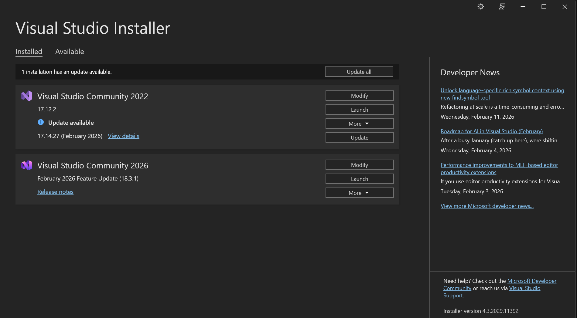
After clicking Launch, it'll prompt you to sign in, and choose Sign in with GitHub. Then, click Clone a Repository
Go to the GitHub repository you are upgrading. Click Code, then copy the HTTPS link and paste it back in Visual Studio.
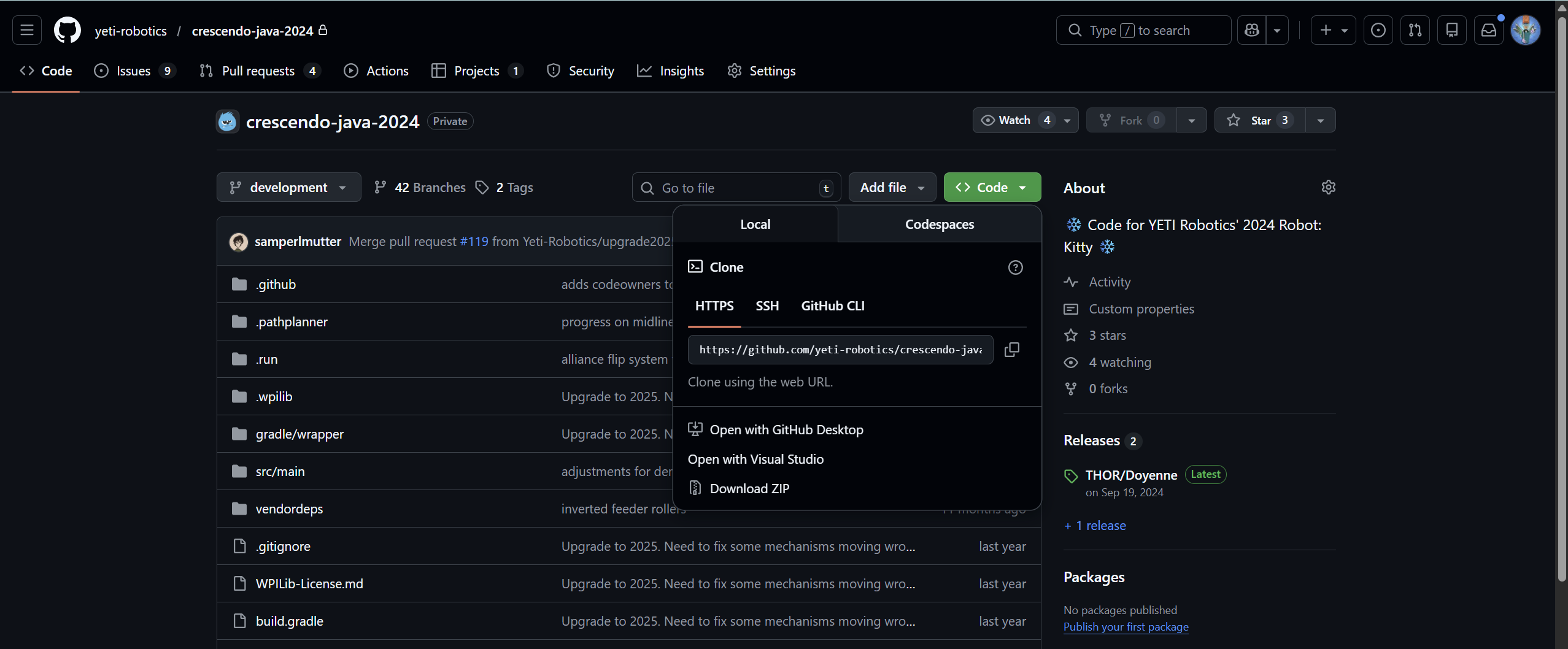
Once the repository is cloned, it should look like this in VS Code.
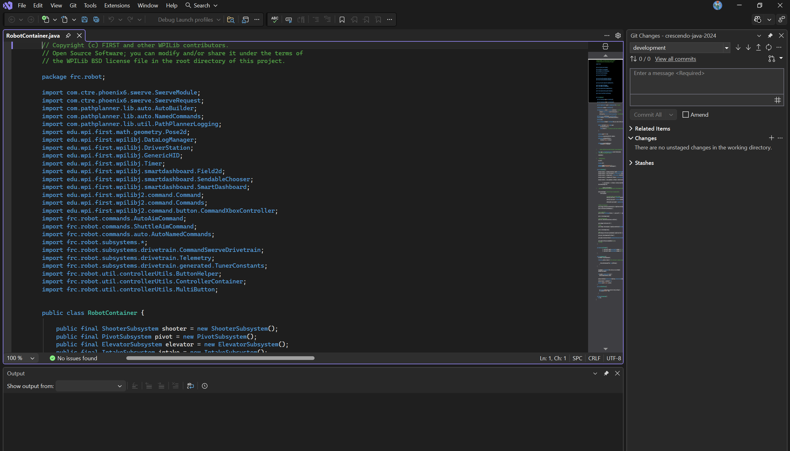
WPILib Extension Download
WPILib Extension Download
The VS Code Extension Marketplace doesn't natively come with the WPILib extension. Search up "WPILib Installer" on your browser of choice. Then, install the latest version and click on the .iso file in your recent downloads.
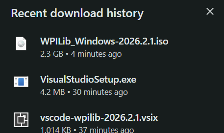
This will take you to your File Explorer, and then double click on WPILibInstaller to run it. Click More Info -> Run Anyway if your computer gives you a warning.
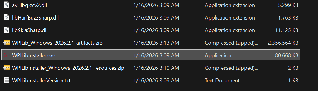
When you get to the following screen, click on "Download for this computer only" and this will begin installing the VS Code extension. Continue with the rest of the installation.
Make sure you close any apps that are using any WPILib stuff before doing this step
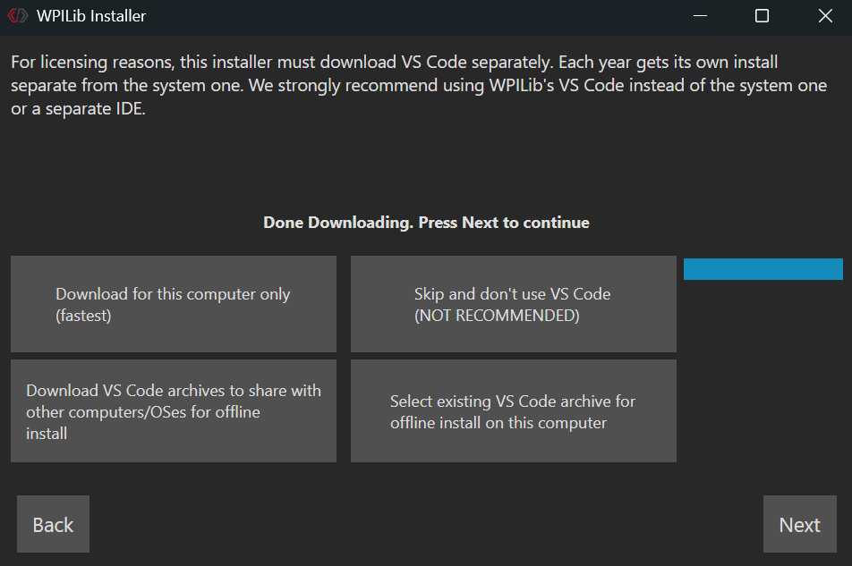
After it tells you that you are finished and you click on the Finish button, open the Start Menu (or its equivalent on Mac) and search up VS Code.
You should see a file named "[Year #] WPILib VS Code". Click and open it. At the bottom, click the Mark Done button.
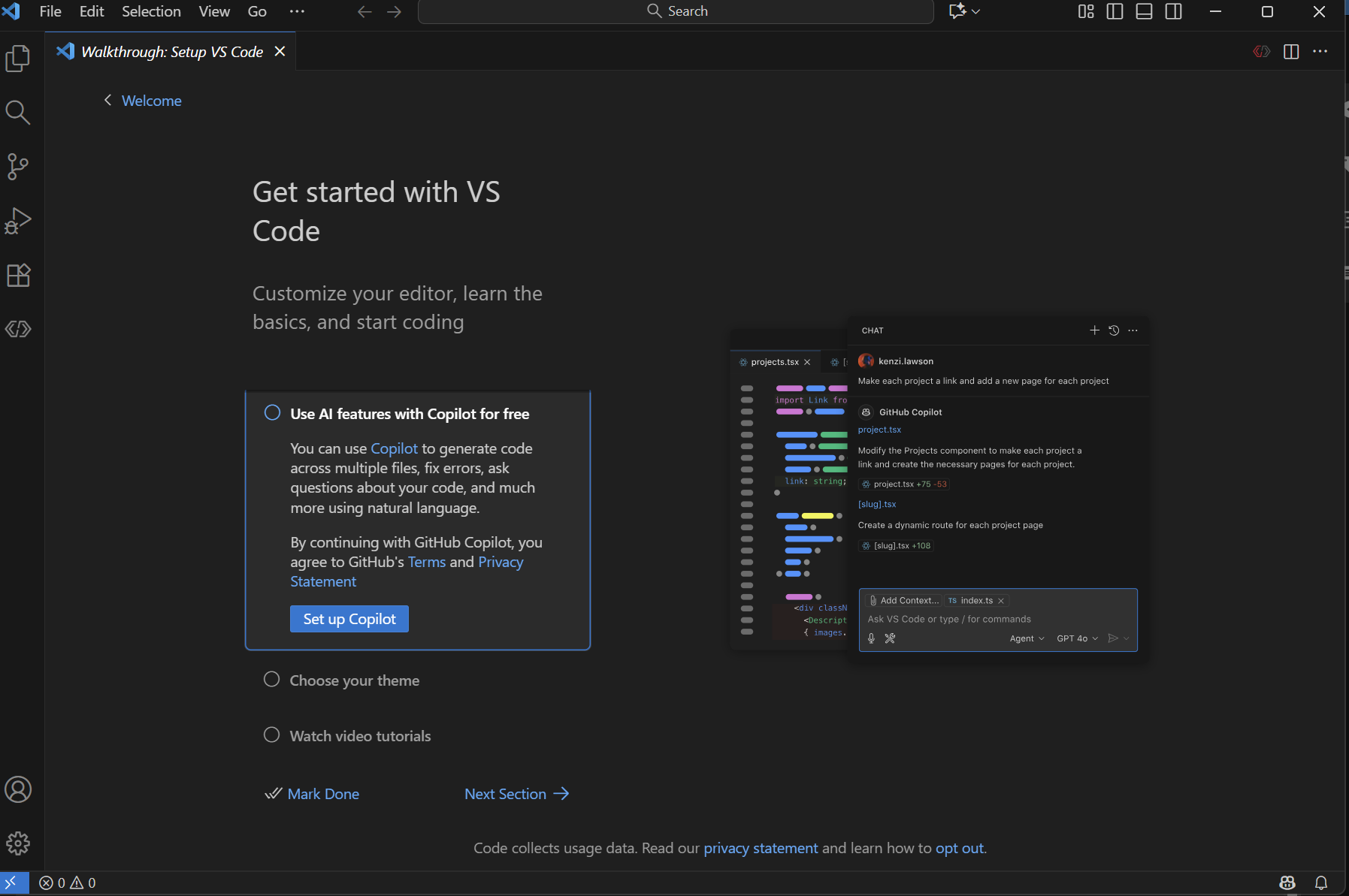
Replacing the Old with the New
Actually Replacing the Old Repositories
Here, click on Clone Git Repository, and follow steps from the previous chapter to copy the HTTPS link and authorize VS Code access to your GitHub account.
Then, you'll see this in the search bar, and select the repository you are upgrading.
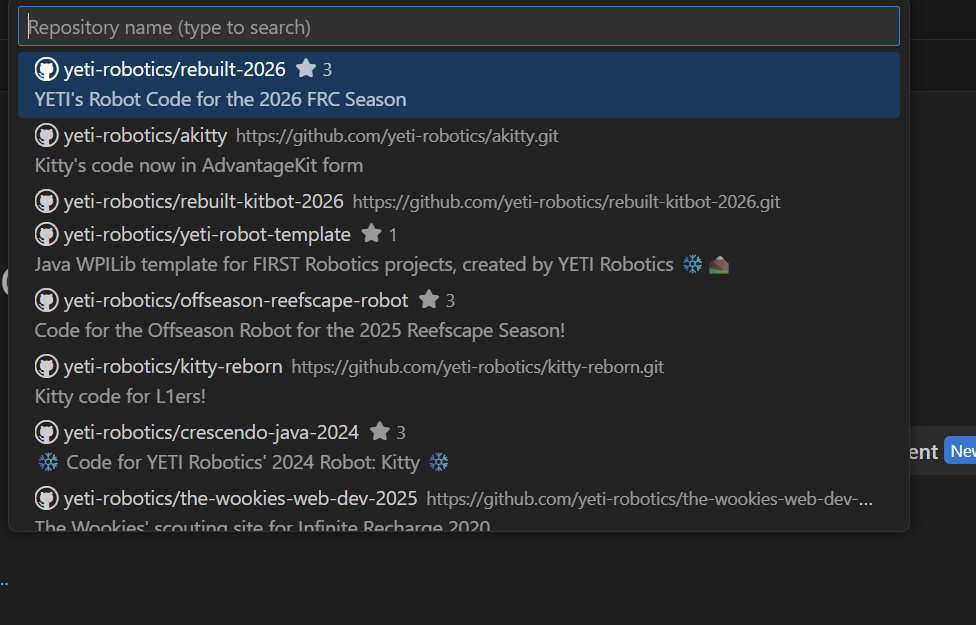
Once you select a target destination folder in your computer (I saved mine in Documents), you'll get a pop-up asking you if you want to upgrade the repo to the current year. Click yes (obviously lol).
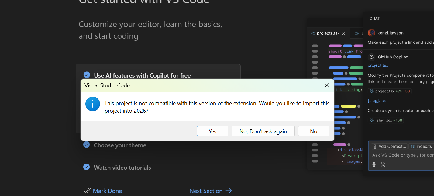
Once you do, it should auto fill out all the fields. The new Project Name for the repository will have an "-Imported" at the end of its name. Then, click Import Project and watch the magic happen.
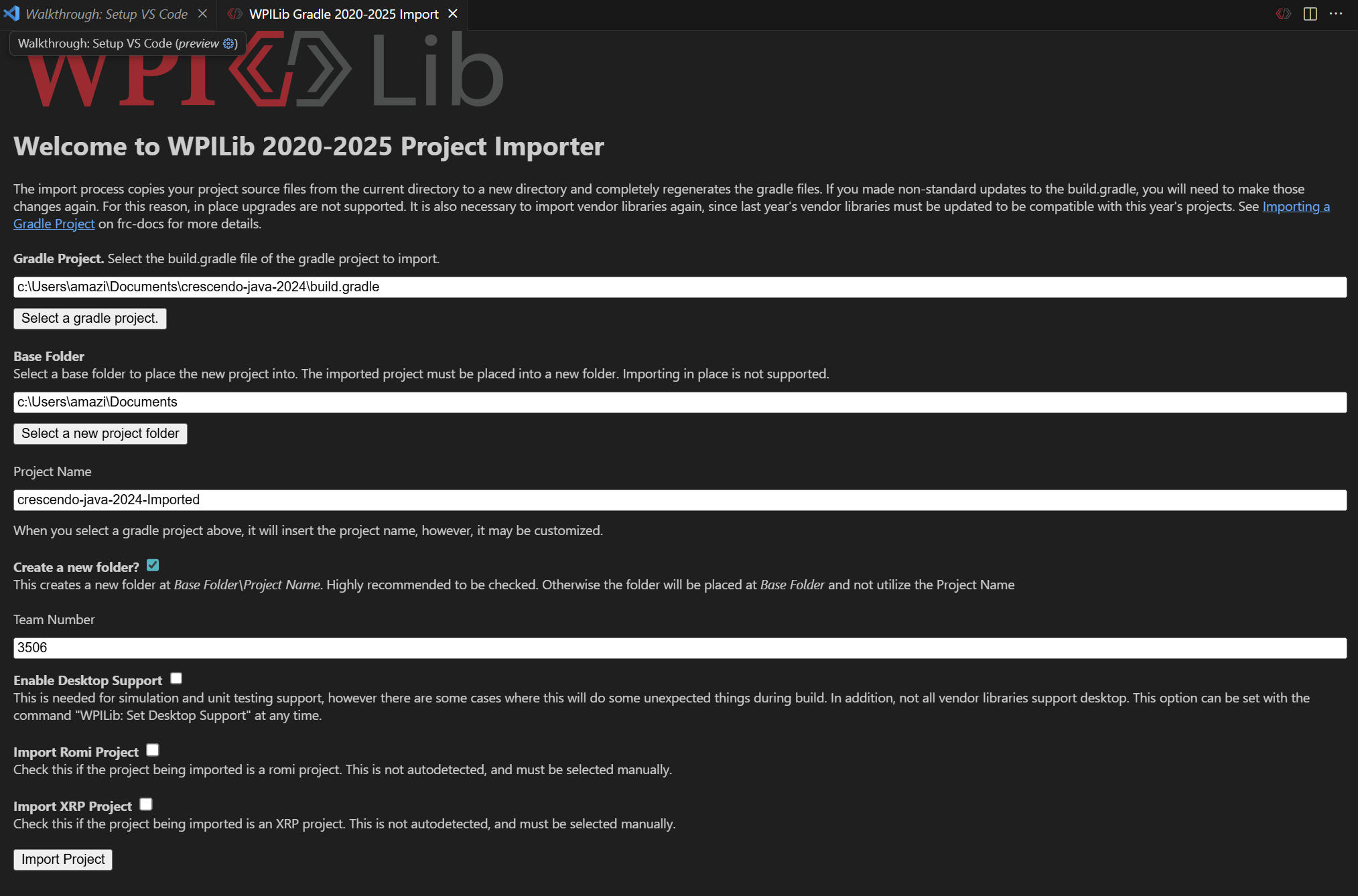
Once the project has finished upgrading, open the repository in your File Explorer.
You will get a bunch of errors in the VS Code project, but don't worry, it's fine.
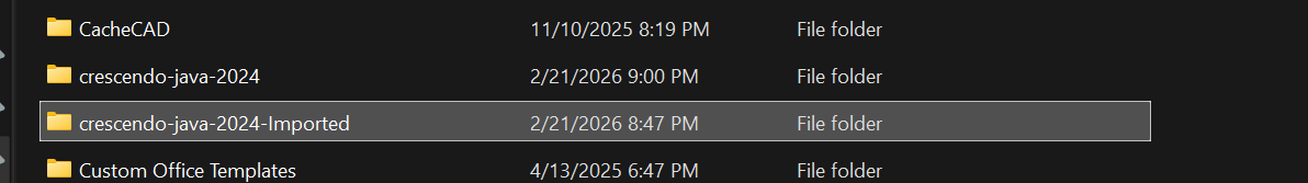
CTRL (or Cmd) + A to select all the files in the "-Imported" repo, and then paste all those new files into the old repo. Click Replace after you paste the files to replace all the old files. To find the old repository in the File Explorer, right click the project name, then Open In -> Explorer
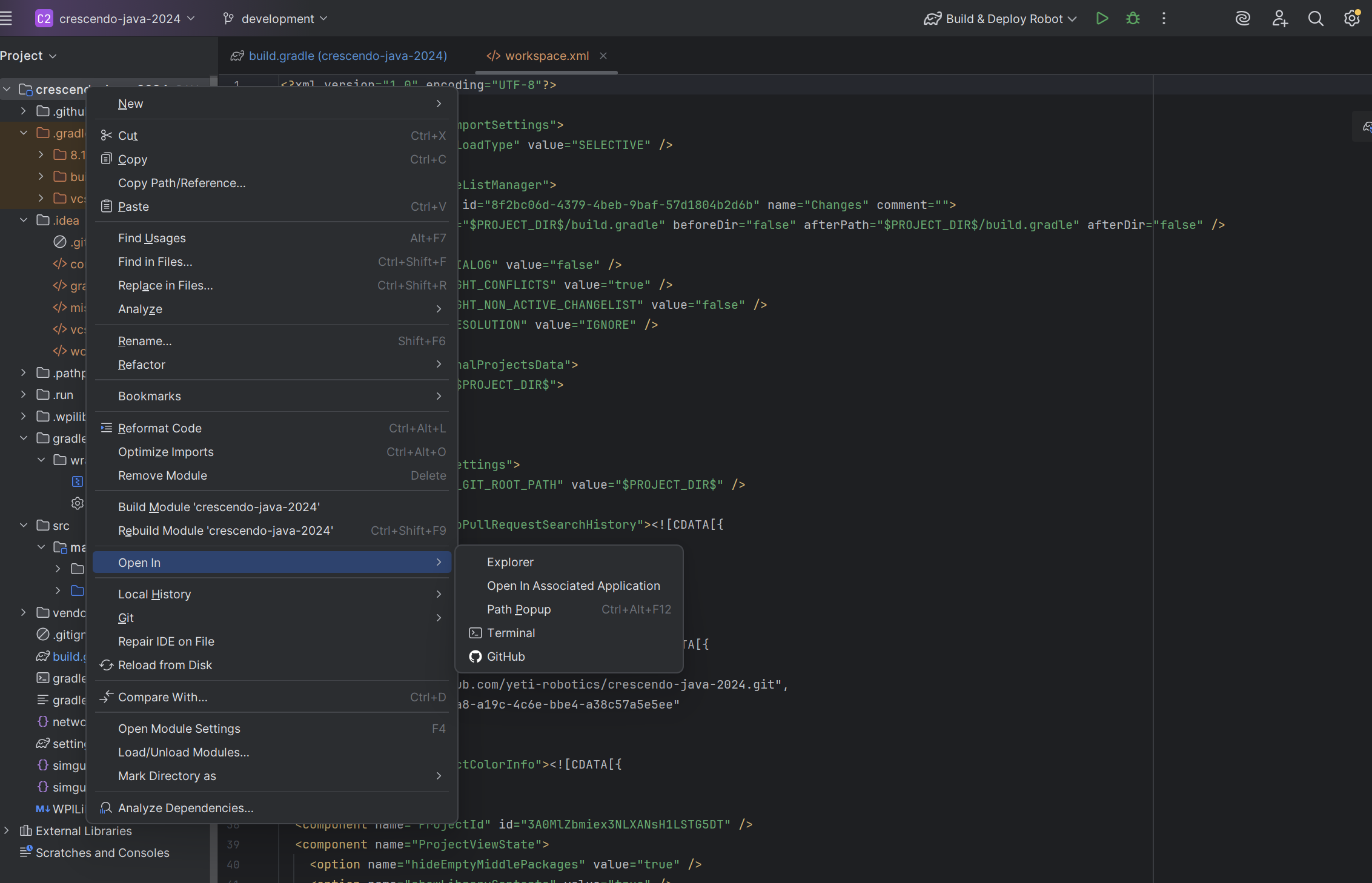
Once you paste all the files into the old repository, reload the gradle and you'll see a couple errors with the VendorDeps.
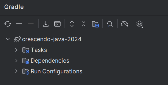
You have to upgrade all old VendorDeps into 2026 by copy and pasting from the team's new repo. (Such as Rebuilt for 2026 upgrade).
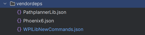
Once you copy/paste the new VendorDeps, reload the gradle again and it will build properly!!
You might have to update deprecated code with new code depending on how old the repo was
Commit your changes, push, and create a PR!