Starting the Schematic: Overall Drivetrain Layout
Hey there! If you're reading this you're trying to create an electrical schematic of your robot! In order to facilitate your journey of creating your electrical schematics, this tutorial is split up into simple sections. The program we utilize as of 2026 is draw.io.
1.0 - Creating a Basic Shape of a Drivetrain
1.1 - Outlining major points of interference (POI's)
1.2 - Identifying Different Types of Drivetrains and How to Depict Different Types
1.3 - Adding the Basic Electrical Components
1.0 - Creating a Basic Shape of a Drivetrain
To begin, you must have a picture of your drivetrain in CAD in order to get a good idea of the shape of your drivetrain. Utilize the shape tools in draw.io to copy the shape of the drivetrain as shown in Figure 1 and Figure 2. For this drivetrain it is a simple square shape but other robots can have different shapes such as 435's 2026 robot which was in shape of a triangle.
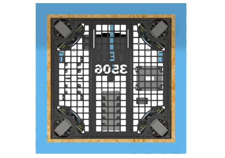
Figure 1

Figure 2
1.1 - Outlining major points of interference (POI's)
In robotics, a Point of Interference (POI) is defined as any area where wiring cannot be routed or is at risk of damage, such as the space beneath an elevator shaft where moving parts could easily crush or sever the cables. When it comes to making schematics POI's are extreme danger zones do not cross zones if you will. No wires or electrical components should be in a POI. As a general rule of thumb any area that may grind, chew, sever, or damage a wire in any way should be avoided.
Let's look at some examples on where to not route wires.
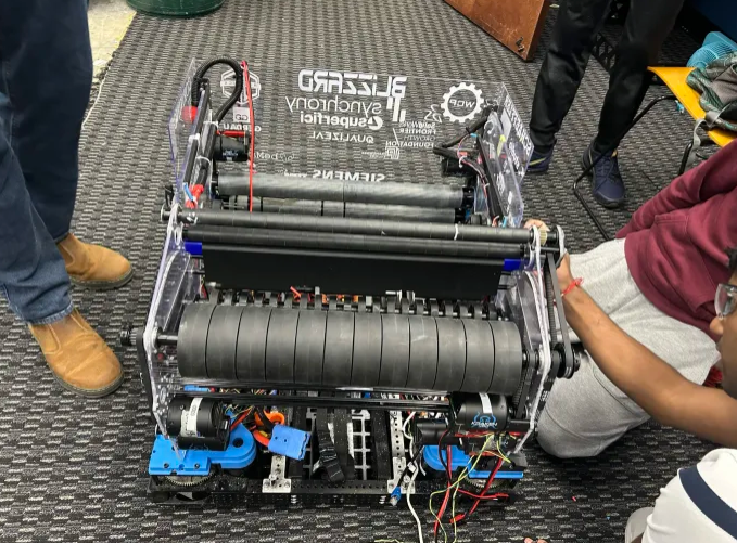
Figure 3
The image shown in Figure 3 is a shooter of one of our robots, Blizzard. Now let's say we take those wires and route them to other components through the flywheels (the large black wheels). This is why knowledge of how mechanical components is beneficial even in electrical. Flywheels would completely destroy wires as they are meant to spin at high revolutions per minute
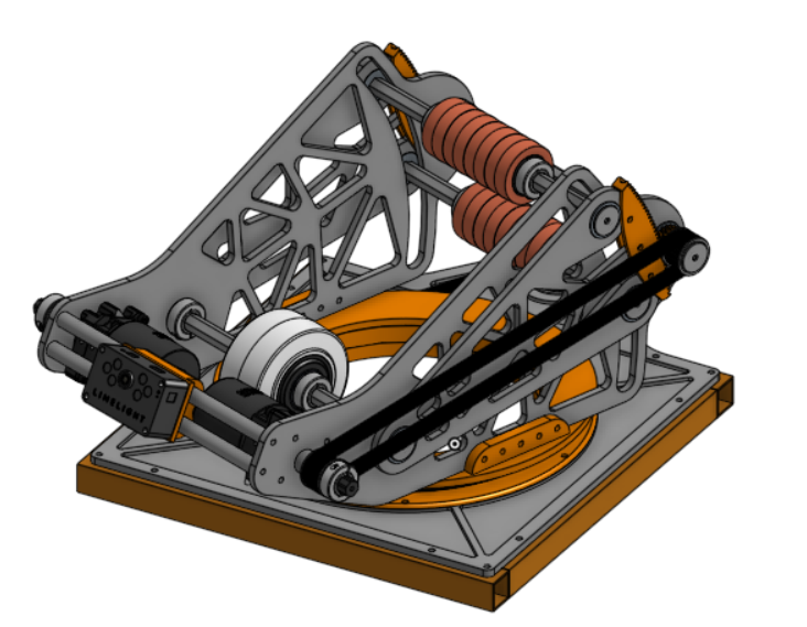
Figure 4
Another example is shown in Figure 4 this is an image of a turret from this year's game. The POI I want to focus on is at the base of the structure. This might not be a very obvious POI at first but when you look closer at it and understand how it functions this turret is designed to rotate. If you wanted to power the mounted limelight on the front you would want to avoid placing wires in the circular orange section. The reason you wouldn't want to do this is because wires can easily get pinched and damaged in between these parts.
If you still have trouble identifying POI's when designing wire routes talk with a veteran in your subteam about where to route and not route wires.
1.2 - Identifying Different Types of Drivetrains and How to Depict Different Types
Note: This is not a full detailed lesson on drivetrains/drivebase designs. This is just a lesson on how to depict drivetrains on a schematic. For more information visit the Drivebase Design page.
In FRC there are many different types of drivetrains but I'll only be highlighting three main types and how to depict them on a schematic. These three main types are Tank Drive, Swerve Drive, and Mecanum Drive. Our robots from 2024, 2025, and 2026 all use Swerve Drive. Below in Figure 5 a drivetrain with tank drive is shown.
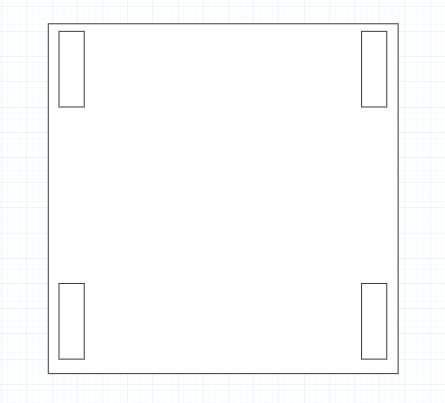
Figure 5
A tank drive consists of 4 or more wheels split evenly between two rows. It's major POI's of this system is outlined above in Figure 5. You don't want to put wires in the wheel areas as they will get damaged in these areas. A 3D image of a tank drive is shown in Figure 6 to better your understanding of how it looks bare.
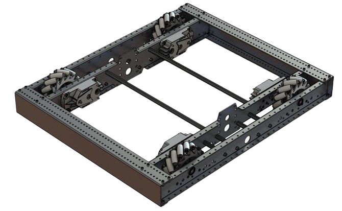
Figure 6
Note: There should always be motors powering these wheels contact your CAD team and discern if they will interfere with your wires or components at all.
Next is Swerve Drive. It contains four different swerve modules for square shaped robots the number of swerve modules can change change for drivetrains with a different shape. In Figure 7 a drivetrain with swerve is shown on a schematic. Then in Figure 8 a bare 3D model is shown.
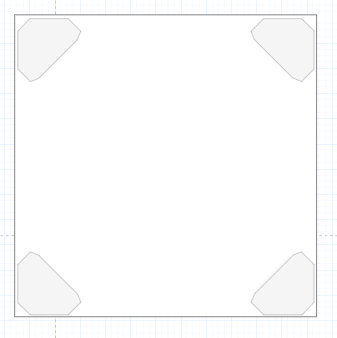
Figure 7
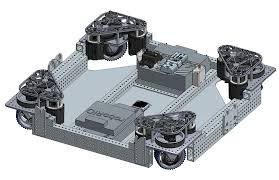
Figure 8
Next is Mecanum Drive.
No Comments