Using CAD in AdvantageScope
Overview
Simulation is very important for YETI, allowing us to test and develop code without a physical robot. Being able to use the CAD created by our team members simulates the actual hardware and can be used to troubleshoot more precisely. The documentation AdvantageScope provides is extremely thorough and it’s always recommended to read the source material. Much of the information found on this page is derived from these docs.
Exporting from SolidWorks
In order to accurately simulate the many moving parts of a robot, the files themselves must be separate. Anything that is an “articulated component”, that provides a degree of freedom and moves independently, such as an elevator, arm, or wrist should be in its own file, and exported as such.
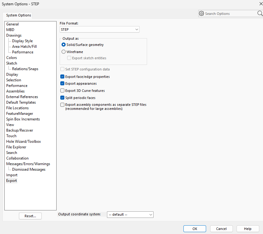
The settings to properly export a component with color are shown below:
Converting to .glb
AdvantageScope uses .glb files for 3D models, and while SolidWorks can export CAD files in that format, the files are often very large and we prefer to first export as STEP and later convert to .glb.
A STEP by STEP :) tutorial for conversion using the application CAD Assistant can be found here.
Configuring the Robot
Configuring your individual components is arguably the most important step, as without doing so you just have a bunch of floating arms and a robot that looks vaguely like a Roomba.
Below is the format the config.json file should be in:
{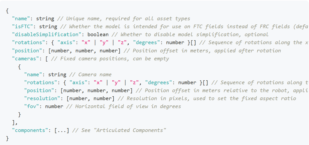
"name": string // Unique name of asset
"isFTC": string // Default is false
"disableSimplification": boolean // optional
"rotations": { "axis": "x" | "y" | "z", "degrees": number } [ ] // Sequence of rotations along the x, y, and z axes
"position": [number, number, number] // Position offset in meters from the origin, applied after rotation
"cameras": [ // Fixed camera positions, can be empty
{
"name": string // Camera name
"rotations": { "axis": "x" | "y" | "z", "degrees": number } [ ] // Sequence of rotations along the x, y, and z axes
"position": [number, number, number] // Position offset in meters relative to the robot, applied after rotation
"resolution": [number, number] // Resolution in pixels, used to set the fixed aspect ratio
"fov": number // Horizontal field of view in degrees
}
],
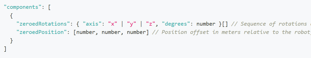
"components": [
{
"zeroedRotations": { "axis": "x" | "y" | "z", "degrees": number } [ ] // Sequence of rotations along the x, y, and z axes
"zeroedPosition": [number, number, number] // Position offset in meters relative to the robot, applied after rotation
}
]
}
Do note that anything in the above format that looks like {something something} [] is a list where you add elements in the format of {something something}. Namely, the rotations are a sequence that contains only the axes that require rotation.
To configure the components, the exact measurements for the positions of the components are needed.
Here, the zeroed position of an arm (portrayed as a wooden block) is circled in red.
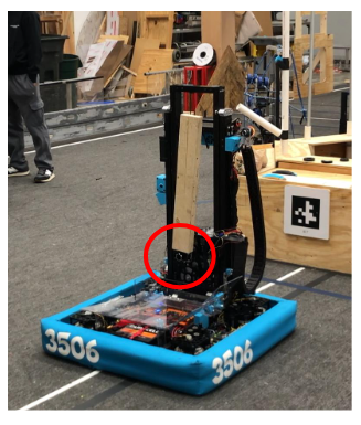
First, the model of the arm must be rotated until it is oriented correctly relative to the robot. If the arm in the file were “lying down”, it would have to be rotated along the y axis, 90 degrees to make it point upwards.
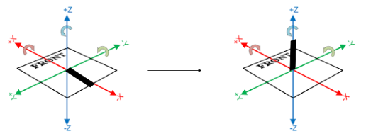
"zeroedRotations": [ { "axis": "y", "degrees": 90} ]
Using the actual measurements of the robot, whether in real life or from CAD, you can fill out the “zeroedPosition” list. In this case, the joint at which the arm is connected is x centimeters back from the center of the robot (on the x axis) and z centimeters up from the base (on the z axis). It’s already centered with the robot “left and right” so there is no translation needed on the y axis.
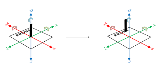
"zeroedPositions": [x, 0, z]
The component for the arm would be
{
"zeroedRotations": [
{ "axis": "y", "degrees": 90}
],
"zeroedPosition": [x,0,z]
}
This process should be repeated for all other components, and the file names of each component model should be “model_INDEX.glb”, the index being that of the component in the array “components” beginning at 0.
A video for all this can be found in the docs for Custom Assets in AdvantageScope that were linked at the beginning of this page: here.